|
|
|
Categories
|
|
Information
|
|
Featured Product
|
|
|
 |
|
|
There are currently no product reviews.
 ;
I was very skeptical of this website, I have never downloaded manuals before. I put it on the AMEX and payed through Paypal to ensure protection. I got the manual exactly as described and now I can replace the filter capacitor for this amp. Great Price, others selling for 12.99 or more and this is the same manual. I will search out this website for other manuals. Thank you
;
Manual was reasonably easy to follow. I am not an engineer or know much about electronics but with the manuals help I was able to figure out the problem, identify the part required for the repair. Replacement part cost around $30. Whilst replacing the part I was telling myself, "this aint gonna work cos it seems far too easy". Took about 15 minutes to do and my plasma TV works a treat. Would never have been able to do this without the service manual.
;
It is OK, this manual help me to repair my dynacord
 ;
Good manual. Even it is an old printed manual, it is well scanned and complete, with all drawings, schematics and parts list. Very good return for the cost.
;
I'm very satisfied with my purchase. It resolved my problem. Owner-manuals.com is a very very good place.
Thank you!
32L-S400, 36L-S400 CL32S40, CL36S40
IMPORTANT SERVICE SAFETY PRECAUTION
(Continued) BEFORE RETURNING THE RECEIVER (Fire & Shock Hazard)
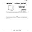
Before returning the receiver to the user, perform the following safety checks. 1. Inspect all lead dress to make certain that leads are not pinched or that hardware is not lodged between the chassis and other metal parts in the receiver. 2. Inspect all protective devices such as non-metallic control knobs, insulating materials, cabinet backs, adjustment and compartment covers or shields, isolation resistor-capacity networks, mechanical insulators, etc. 3. To be sure that no shock hazard exists, check for leakage current in the following manner. � Plug the AC cord directly into a 120 volt AC outlet, (Do not use an isolation transformer for this test). � Using two clip leads, connect a 1.5k ohm, 10 watt resistor paralleled by a 0.15µF capacitor in series with all exposed metal cabinet parts and a known earth ground, such as electrical conduit or electrical ground connected to earth ground. � Use an AC voltmeter having with 5000 ohm per volt, or higher, sensitivity to measure the AC voltage drop across the resistor. � Connect the resistor connection to all exposed metal parts having a return to the chassis (antenna, metal cabinet, screw heads, knobs and control shafts, escutcheon and etc.) and measure the AC voltage drop across the resistor. AII checks must be repeated with the AC ine cord plug connection reversed. (If necessary, a nonpolarized adapter plug must be used only for the purpose of completing these check.) Any current measured must not exceed 0.5 milliamp. Any measurements not within the limits outlined above indicate of a potential shock hazard and corrective action must be taken before returning the instrument to the customer.
1.5k ohm 10W
0.15µF TEST PROBE
TO EXPOSED METAL PARTS
CONNECT TO KNOWN EARTH GROUND
21210987654321098765432109876543212109876543210987654321098765432121098765432109876543210987654321 21210987654321098765432109876543212109876543210987654321098765432121098765432109876543210987654321 21210987654321098765432109876543212109876543210987654321098765432121098765432109876543210987654321
SAFETY NOTICE
Many electrical and mechanical parts in television receivers have special safety-related characteristics. These characteristics are often not evident from visual inspection, nor can protection afforded by them be necessarily increased by using replacement components rated for higher voltage, wattage, etc. Replacement parts which have these special safety characteristics are identified in this manual; electrical components having such features are identified by "Ã¥" and shaded areas in the Replacement Parts Lists and Schematic Diagrams. For continued protection, replacement parts must be identical to those used in the original circuit. The use of substitute replacement parts which do not have the same safety characteristics as the factory recommended replacement parts shown in this service manual, may create shock, fire, X-radiation or other hazards.
21210987654321098765432109876543212109876543210987654321098765432121098765432109876543210987654321 21210987654321098765432109876543212109876543210987654321098765432121098765432109876543210987654321 21210987654321098765432109876543212109876543210987654321098765432121098765432109876543210987654321
3
|
|
|
> |
|