|
|
|
Categories
|
|
Information
|
|
Featured Product
|
|
|
 |
|
|
There are currently no product reviews.
 ;
An excellent service manual contains dismantling locations of components, electronic adjustments,worth the money.
;
Caracteristiques,circuit adjusment,notes on schematis diagram,it's a good service manual,to live well,thanks.
;
Service Manual in good quality, with all of the pages.
;
Very usrfull for repaur, great quality copy. includes complete parts list and schematics
;
Good quality Service Manual, availability of components includes disassembly, electronic adjustments. Includes a full list of details and diagrams. Contains 58 pages.
6557-03N/03S/43N/43S
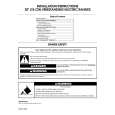
2-7. PICTURE TUBE REMOVAL
4 2
Three connectors CN2 (DY) GND (DY) CN4 (DY)
Two screws (+ BVTT 4 x 8)
3
A board
1
Anode cap
6 7
Neck assy
Deflection yoke
5
Picture tube
� REMOVAL OF ANODE-CAP
NOTE: Short circuit the anode of the picture tube and the anode cap to the metal chassis, CRT shield or carbon painted on the CRT, after removing the anode.
� REMOVING PROCEDURES
c
b
a
Anode Button
1 Turn up one side of the rubber cap in the direction indicated by the arrow a.
2 Using a thumb pull up the rubber cap firmly in the direction indicated by the arrow b.
� HOW TO HANDLE AN ANODE-CAP
1 Don�t hurt the surface of anode-caps with shartp shaped material! 2 Don�t press the rubber hardly not to hurt inside of anode-caps! A material fitting called as shatter-hook terminal is built in the rubber. 3 Don�t turn the foot of rubber over hardly! The shatter-hook terminal will stick out or hurt the rubber.
3 When one side of the rubber cap is separated from the anode button, the anode-cap can be removed by turning up the rubber cap and pulling up it in the direction of the arrow c.
2-4
|
|
|
> |
|