|
|
|
Categories
|
|
Information
|
|
Featured Product
|
|
|
 |
|
|
There are currently no product reviews.
 ;
Incredibly clear!!!! Well done, complete and wonderful. It could not better than this!!!!
 ;
Thank You for fast delivery for the sheme.
Everything allright.
Thanks & best regards Franz
;
again you did a very good job. It was fast too. Photocopy are really readable and clear
;
Probably it never existed a 1081 official service manual from Commodore, it's look more like a NAPCEC service manual & diagrams compilation of the 1084 series and his variants, like the nap6523, 8cm505, 1084S, 1084P and obviously the 1081. It's more complete than other scans and the quality of the scans also are far superior. It has two circuit diagrams variants of the 1081, mono and stereo versions. It doesn't include a diagram for the Philips CM8500 or CM8501, they look like the 1081 but they are slightly different.
;
Rapid, clear well done as all the scheme I downloaded from this site. Great job very functional and very useful
SECTION 3 DISASSEMBLY
3.1 DISASSEMBLY PROCEDURE 3.1.1 REMOVING THE REAR COVER � Unplug the power plug. (1) As shown in Fig.2, take out the 14 screws [A]. (2) Remove the REAR COVER toward you. NOTE : When reinstalling the REAR COVER, carefully push it inward after inserting the chassis into the REAR COVER groove. 3.1.6 REMOVING THE SPEAKER � Remove the REAR COVER. � Remove the CHASSIS BASE. (1) As shown in Fig.2, take out the 4 screws [H]. (2) Follow the same steps when removing the other hand SPEAKER. 3.1.7 CHECKING THE MAIN PW BOARD � To check the backside of the MAIN PWB. (1) Pull out the CHASSIS BASE. (Refer to REMOVING THE CHASSIS BASE). (2) Erect the chassis vertically so that you can easily check from the backside of the MAIN PWB. CAUTION : � When erecting the chassis, be careful so that there will be no contacting with other PWB. � Before turning on power, make sure that the CRT earth wire and other connectors are properly connected. 3.1.8 WIRE CLAMPING AND CABLE TYING (1) Be sure to clamp the wire. (2) Never remove the cable tie used for tying the wires together. Should it be inadvertently removed, be sure to tie the wires with a new cable tie.
3.1.2 REMOVING THE CHASSIS BASE � Remove the REAR COVER. (1) Slightly raise the both sides of the CHASSIS BASE by hand, and teka out the 2 claws [B] (Fig.1 and Fig.2) under the both sides of the chassis from the chassis rail. (2) As shown in Fig.1, draw the CHASSIS BASE backward along the chassis rail [C] (Fig.1) in the arrow direction [D] (Fig.2). (If necessary, detach the wire clamp, connector's etc.) NOTE : When conducting a check with power supplied, be sure to confirm that the CRT earth wire is connected to the CRT SOCKET PWB and the MAIN PWB.
3.1.3 REMOVING THE TERMINAL BOARD � Remove the REAR COVER. (1) As shown in Fig.2, take out the 4 screws [E]. (2) When you pull out the TERMINAL BOARD, it can be removed.
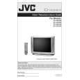
FRONT CABINET
3.1.4 REMOVING THE FRONT CONTROL PW BOARD � Remove the REAR COVER. � Remove the CHASSIS BASE. (1) As shown in Fig.2, take out the 3 screws [F] attached the FRONT CONTROL PWB with the front cabinet. (2) Then remove the FRONT CONTROL PWB.
MAIN PWB
C
3.1.5 REMOVING THE FRONT TERMINAL PW BOARD � Remove the REAR COVER. � Remove the CHASSIS BASE. (1) As shown in Fig.2, take out the 2 screws [G]. (2) Then remove the FRONT TERMINAL PWB.
CHASSIS BASE
B
Fig.1
(No.52121)1-9
|
|
|
> |
|