|
|
|
Categories
|
|
Information
|
|
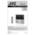
Featured Product
|
|
|
 |
|
|
There are currently no product reviews.
 ;
Fast Download,all pages present,an excellent copy.THis enabled to find the origional part numbers and chase them up. The cartridge is proving difficult to find but at least I know the origional part number.Thanks to all.
;
The manual was as described. Complete with parts list and technical information. Fast delivery.
 ;
Simple and fast...
The diagrams are clear and legible; i have been a great help.
The site is very reliable and precise thanks.
;
Very easy site. Great service and quick release for download. Manuals are of good quality.
Joop - The Netherlands
;
Very good manual, in depth and complete. Only criticism is that some of the circuit diagrams are slightly blurry and hard to follow for long periods of time, but this is to be expected. Perfect for any maintenance required. Also contains the wiring diagrams of the control cable for constructing extensions.
3.1.10 REAR PANEL (1) Loosen 7 screws [ L ]. (2) Remove 6 screws [ M ]. (3) Remove 2 screws [ N ]. (4) Raise slightly REAR PANEL upward. (5) Take out the REAR PANEL. NOTE : � Before the rear panel is inserted into the cabinet, release the short-circuit between the [SB] connector (1) pin and (2) pin of the DIGITAL INPUT UNIT. (Refer to "CAUTION AT DISASSEMBLY" on Page 10). � After releasing the short-circuit between the [SB] connectors, do not turn the power on until the rear panel is inserted into the cabinet. � Prior to starting the work, be sure to read the following written instructions on the CAUTION LABEL attached to the REAR PANEL. Prior to starting the work, be sure to read the following written instructions on the CAUTION LABEL attached to the REAR PANEL. UNPLUG THE POWER CORD FROM AC OUTLET BEFORE OPEN THE REAR COVER (PANEL). When the rear cover (panel) is removed, follow "CAUTION AT DISASSEMBLY" procedure in the service manual before plugging the TV's power cord into an AC outlet. Failure to follow the procedure will result in PERMANENT damage to some of the television features. 3.1.11 PARTITION � Take out the REAR PANEL. (1) Pull out the PARTITION back ward. 3.1.12 REAR COVER � Take out the SPEAKER GRILLE. � Take out the FRONT CONTROL BOX. � Take out the SCREEN ASS'Y. (1) Remove 2 screws [ N ]. (2) Remove 2 screws [ O ] from front side. (3) Slightly pull for backside to disengage of the REAR COVER from hooks. (4) Take out the REAR COVER. NOTE : � Because of the large size, at least two persons are recommended for removal and reassemble.
PARTITION
M O N M
REAR PANEL
REAR COVER BRACKET
Fig.6
REAR COVER
BRACKET
O
Fig.7
1-12 (No.52162)
|
|
|
> |
|