|
|
|
Categories
|
|
Information
|
|
Featured Product
|
|
|
 |
|
|
There are currently no product reviews.
 ;
I found this service manual to be complete in every detail except for troubleshooting charts. It would be helpful if it had a set of troubleshooting charts; however it is a very good manual otherwise and for the price it is very well worth it.
 ;
Complete manual included schematics layouts and alignment procedure, clear to read and magnify, extremely pleased with manual and owner manual . com's service
;
perfect, i am very satisfait for the réception of the sansui r-5l service manual, thank you very much
;
Thank you, this is a rare document. Few others have it, but they charge way more for a download.
Great deal (even if you have to wait a few hours to get it).
;
The purchased manual is an high quality scan of the original Philips paper-based Service Manual. I am very satisfied!
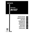
ADJUSTMENT <TUNER / FRONT>
C TUNER C.B G
9 6
CN601 FFE801
L771 TP5 (LCH)
L772
TC942 IC771 TP2 (CLK) TP6 (RCH) (DC BALANCE) TP3 TP4 (DC BALANCE)
(1/3)
TP1 (VT)
L942
L981 L941
35689
9
1
4
3
5
247
< TUNER SECTION >
1. Clock Frequency Check Settings : � Test point : TP2 (CLK) Method : Set to MW 1602kHz and check that the test point is 2052kHz ± 45Hz. 2. MW VT Check Settings : � Test point : TP1 (VT) Method : Set to MW 1602kHz and check that the test point is less than 8.0V. Then set to MW 531kHz and check that the test point is more than 0.6V. 3. MW Tracking Adjustment Settings : � Test point : TP5 (Lch), TP6 (Rch) � Adjustment location : L981 (1/3) Method : Set to MW 999kHz and adjust L981 (1/3) so that the test point becomes maximum. 4. LW VT Adjustment Settings : � Test point : TP1 (VT) � Adjustment location : L942 Method : Set to LW 144kHz and adjust L942 so that the test point becomes 1.3V ± 0.05V. Then set to LW 290kHz and check that the test point is less than 8.0V. 5. LW Tracking Adjustment Settings : � Test point : TP5 (Lch), TP6 (Rch) � Adjustment location : L941 ........................... 144kHz TC942 ......................... 290kHz Method : Set up TC942 to center before adjustment. The level at 144kHz is adjusted to MAX by L941. Then the level at 290kHz is adjusted to MAX by TC942.
6. AM IF Adjustment Settings : � Test point : TP5 (Lch), TP6 (Rch) � Adjustment location : L772 ........................... 450kHz 7. FM VT Check Settings : � Test point : TP1 (VT) Method : Set to FM 108.0MHz and check that the test point is less than 8.0V. Then set to FM 87.5MHz and check that the test point is more than 0.5V. 8. FM Tracking Check Settings : � Test point : TP5 (Lch), TP6 (Rch) Method : Set to FM 98.0MHz and check that the test point is less than 13dBµV. 9. DC Balance / Mono Distortion Adjustment Settings : � Test point : TP3, TP4 (DC balance) : TP5(Lch), TP6(Rch) (Distortion) � Adjustment location : L771 � Input level : 60dBµV Method : Set to FM 98.0MHz and adjust L771 so that the voltage between TP3 and TP4 is 0V ± 300mV. Next, check the distortion is less than 1.3 %.
� 31 �
 $4.99 AV-D37 AIWA
Owner's Manual Complete owner's manual in digital format. The manual will be available for download as PDF file aft…
|
|
|
> |
|