|
|
|
Who's Online
There currently are 6041 guests and
2 members online. |
|
Categories
|
|
Information
|
|
Featured Product
|
|
|
 |
|
|
There are currently no product reviews.
 ;
Great Manual! It contains all the wiring schematics and mechanical exploded views that are essential for service and repair. I was surprised I even found this for such an old machine. Only wish I knew of this site many years ago.
;
Great manual very clear copied. You are making an incredible job. I appreciate a lot the rapidity and your efficiency. Thanks a lot
;
Good pdf of the service manual for this unit. Includes disassembly instructions, full schematics, board layouts, parts lists and diagnostic information. Some information is in the pdf twice (single pages, and split pages), but that could be how it was originally generated by panasonic, or perhaps the idea is to make it eaiser to put onto 8.5 x 11" pages.
Information was exactly what I needed. Delivery was overnight (less than 12 hours) and I was happy with the process.
;
5 STARS for FAST DELIVERY, BEST PRICES and QUALITY PRODUCT. Item was exactly as described with superb resolution. Will definitely source all my future requirements from this website. Thanks a lot owner-manual.com!
;
OEM manual provided all schematics, board layouts and component specs necessary to facilitate unit maintenance. All pages were clear and readable.
5
6
7
8
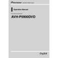
Removing the Holder and the Panel (Fig.4)
1 2 3
Remove the three screws.
3 1
1
2
1
A
Remove the three screws.
2
Remove the two screws and then remove the Panel.
3
2
Panel Holder
4 5
Remove the screw. Straighten the tabs at two locations indicated and then remove the Holder.
5
B
4 5
[Caution] The Panel cannot be removed in 3 unless the Holder is removed in advance in 4 and 5 .
C
Fig.4
Removing the Mother Unit (Fig.5)
1 2 3 4
Disconnect the connector.
D
Remove the two screws.
4 1
Remove the two screws. Straighten the tabs at three locations indicated and then remove the Mother Unit.
4 2 2
3
E
4
3
Mother Unit
Fig.5
F
AVH-P5900DVD/XN/UC
5 6 7 8
63
|
|
|
> |
|