|
|
|
Categories
|
|
Information
|
|
Featured Product
|
|
|
 |
|
|
There are currently no product reviews.
 ;
I was very glad recieving the service manal from You. Additionaly very fast. Extremaly nice servicing. Thanks very mach! Now my GX-220 working better, than it was made. Alexander from Moscow, Russia/
;
Sweet! I won the item on eBay and couldn't adjust the geometry or even keep a steady picure. This guide has the full schematics (not available anywhere else as far as I could tell), and was a bargain for the wealth of knowledge it contains. I hooked it up to my testing equipment, tweaked a few potentiometers and got it playing videogames in no time. Thanks!
;
It was just what I need to fix my old BMW's CD player. Very convenient also. Thank you.
;
Great Manual! It contains all the wiring schematics and mechanical exploded views that are essential for service and repair. I was surprised I even found this for such an old machine. Only wish I knew of this site many years ago.
;
Great manual very clear copied. You are making an incredible job. I appreciate a lot the rapidity and your efficiency. Thanks a lot
4-3. Panel Maintenance Menu
4-3-3. EL Panel Test
An EL panel test is executed. The screen displayed on the EL panel appears while the F6 key is pressed. The displays changes every time the F6 key is pressed. ALL ON : All light. ALL OFF : All go off. V BAR : Displays the test pattern in a vertical line. H BAR : Displays the test pattern in a horizontal line.
4-3-5. Dial Test
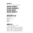
Interface test between search dial and dial interface is executed. 1. Press the F8 key to enter the menu. 2. Confirm the display on the EL panel as follows: Dial data : The numeral changes when the dial is turned. �2Ah� is displayed when the dial is fully turned to right and left. �0h� is displayed when the dial is in the center position. Dial direction : The arrow changes when the dial is turned.�8� is displayed when the dial is on the right of the center click position. �7� is displayed when the dial is on the left of the center click position. JOG/SHUTTLE sensor : JOG is displayed when the dial is pressed. SHUTTLE is displayed when the dial is released. Dial mode sensor : Fix the panel to the 90-degree position, loosen the screw shown in the figure at the back of the dial, and move the mode selection plate. The current display then changes to BETACAM/D-2.
4-3-4. Key Test
Rubber key, illumination switch, illumination switch LED, and other LED tests are executed. 1. Press the F7 key to enter the menu. 2. Press each key sequentially according to the display on the EL panel. 3. Confirm that the buzzer sounds when the key is pressed. Confirm that the switch lights and the buzzer sounds when the illumination key is pressed. 4. Message �Key TEST passed.� is lastly displayed on the EL panel. The test is completed at that time. If abnormality occurs in the key during operation, no sound is generated when the key was pressed. The test can be executed no longer. To terminate the test halfway, press the SHIFT and CLR keys simultaneously.
Lower control panel
A portion Search dial
Mode selection plate B3�14
BKDW-515
4-3
|
|
|
> |
|
|
Parse Time: 0.174 - Number of Queries: 100 - Query Time: 0.032