|
|
|
Categories
|
|
Information
|
|
Featured Product
|
|
|
 |
|
|
There are currently no product reviews.
 ;
Exactly the JVC service manual and schematics that I was looking for - delivered just hours after order. Will do business again!
;
This is a fantastic site, ad I have been a returning satisfied cusumer!
Thanx for a great sevice!
;
Je suis audiophile belge, électronicien et créateur d'enceintes acoustiques.
J'ai apprécié la qualité des documents fournis. Ils sont très lisibles, ils peuvent être agrandis sans problème et ils sont complets. Pour moi, c'est parfait. Pour cette qualité, je suis d'accord de payer. Et le système de paiement et d'envoi est simple. Merci, continuez comme cela.
Frédéric
;
The cover page was a little scary, very dark but readable. The remainder of the document was better copy and easily readable. Why would I give 5 Stars? (1) PRICE, (2) AUTHENTICITY, It was the real deal, filled with service information, including the specific information I required. (3) PRIVACY, I didn't start to get slammed with spam. (4) EASY TRANSACTION. Painless. (5) COMPLETE, I have found several manuals here, that I could find nowhere else. (6) I will be a repeat customer!
;
Well done!!! I found what I need to have, indeed!
Furthermore, due to my hobby is repairing vintage equipments, I added this web site in my desk toolbar because I have in mind to search further service manuals. Thanks a lot www.owner-manuals.com !
Regards, Maurizio
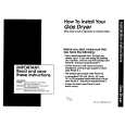
4-13. TG1 Arm, Reel Table (S) Assembly, Push Switch (3Key)
1. Removal procedure
1) 2) 3) 4) 5) 6) 7) 8) 9) Remove the TG1 arm spring 1.
Note: Take note of the position where the spring has been hooked.
2. Attachment procedure
Attach the push switch (3key) qa to the cassette guide T qs with the two claws 0. 2) Attach the cassette guide T qs to the notch of the LS chassis block assembly with the two claws 9. 3) Solder the cassette guide T qs to the LS-057 board at the four locations. 4) Attach the lock guide 7. 5) Attach the BT band assembly 6. 6) Check the location of the reel table S 4. Then, rotate the S ratchet arm 3 in the direction of the arrow A and insert the band of the BT band assembly 6 into the groove on the side. 7) Attach the BT band assembly to the TG1 arm 2 and attach it to the mechanism chassis block assembly. 8) Check the shape of the hook of the TG1 arm spring 1. Hook one end of the spring on the TG1 arm 2. Then, hook the other end of the spring on the same location of the LS chassis block assembly where you have taken note when the spring is removed. 9) Attach the RVS arm spring. 10) Check the TG1 back-tension. (Refer to 5-1.)
Note: The BT band assembly 5 must be completely inserted into the groove on the side of the reel table (S) 4.
1)
Remove the TG1 arm 2. Open the claw of the reel table (S) assembly 4 in the directions of the arrows B and C and remove the reel table S assembly. Remove the RVS arm spring 5. Rotate the S ratchet arm 3 in the direction of the arrow A and remove the BT band assembly 6. Remove the lock guide 7. Remove the four solderings of the LS-057 board. Remove the two claws 9 of the cassette guide T qs from the notch of the LS chassis. Remove the push switch (3key) qa by releasing the two claws of the cassette guide T qs.
B
4 Reel table (S) assembly
Check the location of the reel table (S) assembly.
Reel table (S) assembly is at right angles. Thin
Open the claw of the reel table S in the directions of the arrows B and C.
C
7 Lock guide
qa Push switch (3key) (REC proof) 2 TG1 arm
When attaching it, insert it under the LS chassis assembly.
6 BT band assembly Never coat grease, never attach any
foreign materials nor bend the assembly. Fit here.
5 RVS arm spring 1 TG1 arm spring qs Cassette guide T
9 Two claws
Reel table (S) assembly
Double-hook side
0 Two claws 8 Remove the four solderings
BT band assembly
RVS arm spring Double-hook side TG1 arm TG1 arm spring
Mechanism status before removing the parts.
A 3 Rotate the S ratchet arm in the direction of the arrow A.
When attaching it, coat the hatched portion with grease.
Fig. 4-13.
� 26 �
|
|
|
> |
|