|
|
|
Who's Online
There currently are 5935 guests online. |
|
Categories
|
|
Information
|
|
Featured Product
|
|
|
 |
|
|
There are currently no product reviews.
 ;
Good service manual. I gat all I want. Copy is good, but could be better. All clear and useful. I sincerely recommend.
 ;
The schematic is very helpful and the images are very good.The schematic is very helpful and the images are very good.The schematic is very helpful and the images are very good.The schematic is very helpful and the images are very good.The schematic is very helpful and the images are very good.The schematic is very helpful and the images are very good.
;
Welcome. The scheme is clearly helped me to repair. Worth to download it.
;
Excellent manual, very clear, technical specification provided, useful information regarding adjustment and set up.
;
fast and easy and exactly what I was looking for. Not the cheapest but value for money after all.
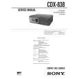
SECTION 6 ELECTRICAL ADJUSTMENTS
Note: 1. Perform adjustments as given. 2. Power supply voltage: DC14.4 V (more than 3A).
� TRACKING OFFSET CHECK � RF BOARD (Conductor Side) �
oscilloscope CNJ12 + � BP11 (TE) TP (VC)
� FOCUS GAIN ADJUSTMENT (COARSE ADJUSTMENT) This adjustment is to be performed when replacing the following parts. � Optical Pick-up Block � RV14 � RF BOARD (Conductor Side) �
CNJ12
� When gain is lowered... The set does not play because of no focus operation. � When gain is highered... Operation noise is heard due to a scratch or a dust, then operation will be unstable.
� FOCUS BIAS CHECK � RF BOARD (Conductor Side) �
oscilloscope CNJ12 TP (RF) + �
IC51
TP (VC) IC11
Procedure: 1. Connect the oscilloscope to BP11 (TE) and TP (VC) on the RF board. 2. Put the set into play mode by loading the disc. 3. Press the . AMS > button, and check the traverse waveform*. 4. Confirm that the oscilloscope waveform is symmetrical on the top and bottom in relation to 0 V dc, and check this level.
* Traverse waveform: This is the tracking error wave form appears when crossing the track.
RV14
IC51
IC11
IC11
Procedure: 1. Connect the oscilloscope to TP (RF) and TP (VC) on the RF board. 2. Put the set into play mode by loading the disc. 3. Confirm that oscilloscope waveform is clear and check RF signal level is correct or not.
Note: Clear RF signal waveform means that the shape ��� can be clearly distinguished at the center of the waveform.
Procedure: 1. Set RV14 (RF board) to the standard position. 2. Check that there is not an abnormal amount of operation noise (white noise) from the 2-axis devise. If there is, turn RV14 slightly clockwise. � RF BOARD (Conductor Side) �
IC51
Traverse waveform VOLT/DIV : 500 mV TIME/DIV : 2 ms Center : 0 V
RF signal waveform VOLT/DIV: 200 mV TIME/DIV: 500 ns level: 1.4 ± 0.3 Vp-p
A=B A 0V B
MIN side (low gain)
traverse waveform (100 track jump waveform)
MAX side (high gain)
RV14 standard position
15
15
 $4.99 CDX-838 SONY
Owner's Manual Complete owner's manual in digital format. The manual will be available for download as PDF file aft…
|
|
|
> |
|