|
|
|
Categories
|
|
Information
|
|
Featured Product
|
|
|
 |
|
|
There are currently no product reviews.
 ;
The quality of the manual is top. The transfer worked perfect and fast.
No problems at all. Recommendable
 ;
Very good service for get any documentation. Fast and perfect quality.
 ;
Excellent service manual with all the necessary info. :)
 ;
The product dowload was delivered efficiently with emails to support its download availabilty. The contets of the manual was very eligible and of good quality. Will purchase from this site again!
 ;
hello this Service Manual PIONER KXE60 is very good, thanks.
ELECTRICAL ADJUSTMENT-2/4 (HRJ, LH, U)
< TUNER SECTION >
1. AM IF Adjustment L007 ............................................................ 1400/1404kHz 2. AM VT Adjustment Settings: � Test point: C39+ � Adjustment location: L004 Method: Set to AM 1602/1710kHz adjust L004 so that the test point becomes 6.0V±50mV (U, LH) set to AM 1602/ 1710 kHz adjust L004 so that the Test point becomes 5.6V±50mV (HRJ). 3. AM Tracking Adjustment L003 ....................................................................... 600kHz TC001 ................................................................... 1400kHz 4. FM VT Adjustment Settings: � Test point: C39+ � Adjustment location: L006 Method: Set to FM 108MHz adjust L006 so that the test point becomes 6.0V±50mV. 5. FM Tracking Adjustment L005 ..................................................................... 87.5MHz
< DECK SECTION >
6. Tape speed Adjustment Settings: � Test tape: TTA-100 � Test point: PHONES JACK (J201) � Adjustment location: SFR of deck motor Method: Play back the test tape and adjust so that the output frequency is 3000Hz ±30Hz. 7. Azimuth Adjustment Settings: � Test tape: TTA-320 � Test point: PHONES JACK (J201) � Adjustment location: Azimuth adjustment screw Method: Play back the test tape and adjust so that the output is maximum.
< CD SECTION >
8. Focus BIAS Adjustment Settings: � Test CD: D-782 � Test point: C441 (RF OUT) C433- (VREF) � Adjustment location: SFR430 Method: Play back the test CD track 2 and adjust so that the output level is DC 0mV±10mV.
-24-
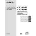
 $4.99 CSDFD82 AIWA
Owner's Manual Complete owner's manual in digital format. The manual will be available for download as PDF file aft…
|
|
 |
> |
|
|
Parse Time: 0.195 - Number of Queries: 104 - Query Time: 0.031
