|
|
|
Who's Online
There currently are 5978 guests online. |
|
Categories
|
|
Information
|
|
Featured Product
|
|
|
 |
|
|
There are currently no product reviews.
 ;
as always, rapid and efficient, very good and clear prints
details clearly visible keep going this way!!!!!!
 ;
I expect a wonderful result as alaways!!!!!!
Usually is much faster....
 ;
Wow very wonderful and clear!!!! I will always trust them
 ;
Providing the manual works fine, quickly and without any problems for an acceptable price. After printing the service manual it took me only a short time to repair my carradio from Clarion. Thank You! Greetings from Heiko
 ;
I was searching a way to modify the original phono-in entry (for connection of vynil disc player, with RIAA equalization) to a line-in entry (for connection of modern analog entries, eg. ipod, mp3player).
This service manual gave me the correct hints.
It contains very useful infos for repairing and modifing the hi-fi, such as disassembling instructions, block diagrams, schematic diagrams, PCB prints, replacement parts list.
Very good!
Pin No.
36 37 38 39 40 41 42 43 44 45 46 47 48 49 50 51 52 53 54 55 56 57 58 59 60 61 62 63 64
Pin Name
LVDD LCHO LVSS RVSS RCHO RVDD MUTER XVDD XOUT XIN XVSS SBSY EFLG PW SFSY SBCK FSX WRQ RWC SQOUT COIN CQCK RES T11 16M 4.2M T5 CS T1
I/O
� O � � O � O � O
Description
Left channel 1-bit D/A converter power supply. Left channel 1-bit D/A converter output. Left channel 1-bit D/A converter ground. Normally, 0V. Right channel 1-bit D/A converter ground. Normally, 0V. Right channel 1-bit D/A converter output. Right channel 1-bit D/A converter power supply. Right channel 1-bit D/A converter muting output. (Not used) Power supply of crystal oscillator. For the connection of a 16.93MHz crystal oscillator.
I � O O O O I O O I O I I input. I O O O I I I LC78622NE reset input. Test output. Set to open (normally, "L" output.) (Not used) 16.9344MHz output. (Not used) 4.2336MHz output. Test input. A pull-down resistor is incorporated. (Connected to 0V) Chip select input. (Connected to 0V) Test input with no pull-down resistor. (Connected to 0V) Ground of crystal oscillator. Normally, 0V. Subcode block sync signal output. (Not used) C1, C2, single, duplex correction monitor. (Not used) Output of subcodes P, Q, R, S, T, U and W. (Not used) Subcode frame sync signal output. Falls when the subcode is set to the standby state. (Not used) Subcode read-out clock input. Schmitt trigger input. ("L" is applied when not used.) (Connected to 0V) 7.35kHz sync signal output obtained by dividing the oscillator frequency. (Not used) Subcode Q standby output. Read/write control input. Schmitt trigger input. Subcode Q output. Command input from the microprocessor. Command input retrieval clock or subcode retrieval clock input from SQOUT. Schmitt trigger
� 22 �
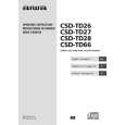
 $4.99 CSDTD27 AIWA
Owner's Manual Complete owner's manual in digital format. The manual will be available for download as PDF file aft…
|
|
 |
> |
|
