|
|
|
Categories
|
|
Information
|
|
Featured Product
|
|
|
 |
|
|
There are currently no product reviews.
 ;
Up to now you are the BEST! Prompt-efficient and so reasonable ! I have been after SONY service manual for quite some time !Thank you very much ! I can recomend your service to
all my collegagues ! V.Bergfield .
 ;
This is a very good quality print (scan) of the original SONY service manual. The original from Sony is on very thin paper. Nevertheless it is very clear and sharp and excellent readable. I'm very satisfied to have now this rare document. I've looking for it many years (infrequent). It contains very detailed circuit diagrams, exploded views, part lists, PCB view with good readable connection lines. Very recommended.
 ;
A complete manual with all the needed details of calibrations and service instructions about the radio receiver.
A big deal.
Many thanks !
 ;
Fast delivery and good quality copy. To be recommended
 ;
Excellent product, very clear print. Detailed circuit and assembly diagrams - this enabled me to repair my CD player with confidence. I highly recommend this site.
FIlter Block Since the sound signall from the CPU is a stepped waveform, the filter block is added to smooth the waveform.
VDD
2SC3112B 10K 10K 6.2K
C331J
C222(H)
C562(H)
From the CPU
To main volume
1K AG AG AG
Initial Reset Circuit When batteries are set or an AC adapter is connected, the reset IC provides a low pulse to the CPU. The CPU then initializes its internal circuit.
VDD Battery set
Reset IC S8053ANO IC4
CPU MSM6626-01 LSI1
RESET
Power On/Off Circuit When the power switch is turned on, a low level differential pulse is provided to terminal MI of the CPU. Upon receipt of the pulse, the CPU starts the power ON sequence and raises the APO signal to +5 V. When the switch is off, on receiving the KO11 signal at terminal KI0, the CPU drops the APO signal to ground level to shut down power.
VDD VDD
ON
Power Switch
OFF ON MI
CPU
KO18 KI0
MSM6626-01 LSI1 APO signal OFF: 0V ON: +5 V
OFF ON
KI1 KO11
�5�
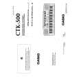
 $4.99 CTK500 CASIO
Owner's Manual Complete owner's manual in digital format. The manual will be available for download as PDF file aft…
|
|
 |
> |
|
|
Parse Time: 0.168 - Number of Queries: 109 - Query Time: 0.036
