|
|
|
Who's Online
There currently are 6040 guests and
3 members online. |
|
Categories
|
|
Information
|
|
Featured Product
|
|
|
 |
|
|
There are currently no product reviews.
 ;
This is a good quality scan of the Operation & Maintenance (Service) Manual for the PAL version of this high-band broadcast umatic, BVU-800P
All schematics and lineup procedures appear to be included in this one manual AFAICT.
The file size is just over 113 MB which gives an idea of the quality and number of pages.
All of the schematics, which contain some fairly small print, are easily readable when you zoom into the page.
John Thompson, Newcastle Upon Tyne, England.
 ;
Good quality, all schematics of few of models. There is also short form of user manual and regulation manual.
 ;
Perfect copy of the service manual. you can enlarge every page, and it comes up
with all details.
 ;
It´s very very nice manual with all, what i need. Original in good quality. Very fast business. Very much thanks...
 ;
Purchased the manual that I was looking for at a great price and could download it easily.. Great service experience and for future purchases I plan to use the site.
Thank you very much
Electrical
Current Drain with 12V DC: No Sound Output Maximum Volume with white keys D2 to D3 pressed in Synth-Bass-2 tone and in Latin Fusion rhythm at initial setup tempo Volume; maximum, Touch: maximum Line Output Level (Vrms with 47 K� load each cannel): with key D4 pressed in FSynth-Bass-2 tone on L-ch with key G4 pressed in FSynth-Bass-2 tone on R-ch Phone Output Level (Vrms with 8 � load each channel): with key D4 pressed in FSynth-Bass-2 tone on L-ch with key G4 pressed in FSynth-Bass-2 tone on R-ch Speaker Input Level: with key D4 pressed in FSynth-Bass-2 tone on L-ch with key G4 pressed in FSynth-Bass-2 tone on R-ch Minimum Operating Voltage:
I S
390 mA ± 20% 1700 mA ± 20%
Note: To increase productivity ,the DSP HG51A115A01FD is sticked on the main PCB with a double-side adhesive tape, then its leads are soldered. Remove the DSP according to the following procedures. 1. Prepare isopropyl alcohol and a flat IC desoldering machine (Spot Heater HS-600). 2. Apply plenty of the alcohol to the adhesive tape from the reverse side of the main PCB. (Fig. 1) There is a hole on the PCB just under the LSI, and the adhesive tape can be seen through the hole. 3. Leave it more than one minute so that the alcohol weaken adhesive power fully. 4. Using a proper size of nozzle, apply heat to leads of the LSI with the desoldering machine. 5. Grasp the LSI with tweezers, and using gentle force vibrate the tweezers to feel melting solder. (Fig.2) 6. Remove the LSI after meltingsolder at every leads wholly.
H G
1 1 5 A
850 mV ± 20% 800 mV ± 20% 280 mV ± 20% 260 mV ± 20% 5200 mV ± 20% 5600 mV ± 20% 5.5 V
REPLACING THE DSP (HG51A115A01FD)
Spot Heater HS-600
Alcohl
1 5A
L S
Fig.1
Fig.2
�2�
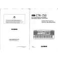
 $4.99 CTK750 CASIO
Owner's Manual Complete owner's manual in digital format. The manual will be available for download as PDF file aft…
|
|
 |
> |
|
