|
|
|
Categories
|
|
Information
|
|
Featured Product
|
|
|
 |
|
|
There are currently no product reviews.
 ;
This document is just what I was looking for, it´s very useful, it contains adjustment procedures for the final stage of the power amp and also
has a complete wiring diagram and description of the main semiconductors used in the design.
;
Dear Sirs,
Thank you for the fast support, the manual does provide all necessary information to repair the radio. All schematics are in a good quality for reading.
The manual fits 100% to my requirements as a technican.
Kind regards Thomas
;
the big video recorder format s-vhs many features delicate in loading system of the cassette. Such machines are no longer manufactured, it would be too expensive.
 ;
THIS MANUAL IS VERY GOOD AND VERY CLEAR
PLEASE NOTE IT DOES NOT CONTAIN THE SETUP INFORMATION TO ALIGHN THE GEARS IN THE CD MECH IT DOES SHOW ALL THE PARTS AND THEIR LOCATIONS .
;
Complete service and operation manual. All schematics are there, all circuit boards AND add-on boards. Including exploded views ,component names and specifications. Also electrical and mechanical adjustment procedures are in this manual. This manual also covers the more advanced BR-S811E unit. Scan quality is fair and usable.
DCR-DVD100/DVD100E
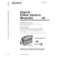
2-18.LB-084 BOARD (REMOVING OF THE EVF)-2
4
Visibility knob (40)
VF slide cabinet (upper) assembly To raise the VF slide cabinet (upper) assembly, insert a flat head (-) screwdriver into the position shown by the arrow. VF slide cabinet (upper) assembly
2A 1 Tapping screw (M1.7 � 3.5) 5C
3 B
2 A
VF slide cabinet (lower)
2 Open the lock of the VF slide cabinet (lower) in the direction of the arrow A, 3 while slanting the VF slide cabinet (upper) assembly in the direction of the arrow B, 4 remove the Visibility knob (40) from the VF slide cabinet (lower), and 5 remove the VF slide cabinet (upper) assembly by sliding it in the direction of the arrow C.
VF slide cabinet (lower)
RE-ASSEMBLING THE VF SLIDE CABINET
1 VF slide assembly
2 Align the dotted portion of the VF slide assembly with the dotted line of the VF slide cabinet (lower).
VF slide cabinet (lower)
When re-assembling, slide the Visibility knob (40) to the fully right-end beforehand. Visibility knob (40) When re-assembling is completed, the VF slide cabinet (upper) assembly and the VF slide cabinet (lower) are assembled as shown. VF slide cabinet (upper) assembly
3 Slide the VF slide cabinet assembly up to the position in the direction of the arrow where the two claws are locked.
4 Tapping screw (M1.7 � 3.5)
VF slide cabinet (lower) VF slide cabinet (lower) Two claws
2-13
|
|
|
> |
|