|
|
|
Categories
|
|
Information
|
|
Featured Product
|
|
|
 |
|
|
There are currently no product reviews.
 ;
Excellent product, very clear print. Detailed circuit and assembly diagrams - this enabled me to repair my CD player with confidence. I highly recommend this site.
;
Fast access, 100% correct and complete service manual
;
just what i was seeking .had a password issue but the review allowed me to circumvent and download was great
;
Great manual, great price. Has a few of the basic operating instructions that most service manuals leave out. Complete instructions for disassembling board by board, safety precautions, schematics, complete parts list.
;
I am very pleased with the service manual for my RT-909. This was an easy purchase and great procuct, and much cheaper than other venues i had looked at. This web site is now listed in my favorites list. KEEP UP THE GOOD WORK. THANKS. J. BROWN
1
2
3
4
1.1.3 Focus error amplifier
The photo-detector outputs (A + C) and (B + D) are passed through the differential amplifier and the error amplifier, and (A + C - B - D) is provided from the pin 135 as the FE signal. The low frequency component of the voltage FE is calculated as below. FE = (A + C - B - D) x 8.8k / 10k x 111k / 61k x 160k / 72k = (A + C - B - D) x 3.5 For the FE outputs, an S-shaped curve of 1.5 Vp-p is obtained with the REFO as the reference. The cutoff frequency for the subsequent stage amplifiers is 14.6 kHz.
A
1.1.4 RFOK circuit
This circuit generates the RFOK signal, which indicates the timing to close the focus loop and focus-close status during the play mode, from the pin 70. As for the signal, "H" is output in closing the focus loop and during the play mode.
B
Additionally, the RFOK becomes "H" even in a non-pit area, since the DC level of the RFO signal is peak-held in the subsequent digital block and compared at a certain threshold level to generate the RFOK signal. Therefore, the focus is closed even on a mirror-surface area of a disc. This signal is also supplied to the microcomputer via the low-pass filer as the FOK signal, which is used for protection and gain switching of the RF amplifier.
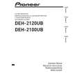
1.1.5 Tracking error amplifier
The photo-detector outputs E and F are passed through the differential amplifier and the error amplifier to obtain (E - F), and then provided from the pin 138 as the TE signal. The low frequency component of the voltage TE is calculated as below.
C
TEO = (E - F) x 63k / 112k x 160k / 160k x 181k / 45.4k x 160k / 80k = (E - F) x 4.48 For the TE output, TE waveform of about 1.3 Vp-p with the REFO as the reference. The cutoff frequency in the subsequent is 21.1 kHz.
CD CORE UNIT
PE5611B
TE A/D
+ -
Pickup Unit
D
P5 P10
+ -
TEOFF setup
+ 80k
138
TEO
47p
160k 137
TE-
E
11
11
E
132 112k 63k
45.36k
161k
VREF
+ 45.36k
+ -
139
TE2
2.7k
+
P1 P6
-
160k
160k 20k 60k 10000p 140
1000p
F
9
9
F
131 112k 63k
TEC
-
VREF
+
Inside TEC
E
Fig.1.1.3 TE
F
6
CX-3240
1 2 3 4
|
|
|
> |
|