|
There are currently no product reviews.
 ;
Detailed schematic diagram, manual for professionals
;
Good service manual,exploded view,adjusment and test point locations,head alignment,mechanical checks and adjusments,all perfect.
;
Block diagram,play rec block diagram,adjusments, it's a very good well done repair manual.
;
Very clear copy of the philips service manual. Fast delivery. Thank you very much
;
Excellent manual, detailed, very useful! Exactly what I needed, I'd recommend it to all who need it. Although images are scanned easily readable and explicit. A valuable tool product at a price more than modest, take it with confidence and you will not regret it!
CX-977
Fig. 5: RFRP and RFCT circuit
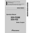
5) SBAD Signal Circuit unit
In this unit, outputs from the photo detector, namely, E and F are processed through the addition amplifier. That is, E and F are added together and (E+F) signal is output from #15 pin of IC101 (TA2153FN), as SBAD signal. This SBAD signal, along with Focus Error signal, is used as one of the conditions that the system uses to internally judge Focus ON/OFF based on them. Also, SBAD signal is used to detect defects: defects that may be detected when the Pickup passes a scratch on the disk, for instance.
Fig. 6: SBAD circuit
5
|