|
|
|
Categories
|
|
Information
|
|
Featured Product
|
|
|
 |
|
|
There are currently no product reviews.
 ;
The manual for Sony LBT-D505 component stereo system is was excellent , with schematics, parts layout and parts list as well as instructions for adjustments for each component. Print was clear even when enlarged.
;
It's exactly a complete and very useful manual with all details what I needed. Thank you!I will come back whenever I need your manuals or schematics.
;
I searched EVERYWHERE looking for the manual/s on this "extinct" amp. Owner-Manuals.com made it available and for nearly nothing. Thanx to them, I can decipher the unknown cables and sort them out. Thanx, Owner-Manuals.com!!
;
Yes thank you i got the file i was after. There was a slight problem in my communication but it all worked out well.
A job well done.
 ;
Great manual...really saved me. The only problem is that I thought I would be able to download it directly when I paid for it but never received the download instructions until the next morning. The board trace pages were somewhat light also: really need to turn up the contrast on the printer before printing them. The schematic page was great; very clear! Well worth the money.
DTR-5.4 ADJUSTMENT AND CONFIRMATION PROCEDURES 1
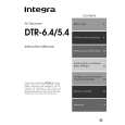
Idling current adjustment Before Idling adjustment, turn the trimming resistors R6040 to R6045 to counter clockwise. Connect the DC voltmeter to sockets P6080 to P6085. After turn POWER to ON, adjust the trimming resistors R6040, R6041 and R6042 so that the reading of voltmeter becomes 2.5 mV. (Front and center channels) Adjust the trimming resistors R6043, R6044 and R6045 so that the reading of voltmeter becomes 1.5 mV. (Surround and surround back channels) After adjustment, attach the top cover. Confirm the voltage of points above after about five minutes. Front and center channels When less than 10.0 mV, readjust the resistors above so that the voltage becomes 10.0 mV. When 10.0 mV to 12.0 mV, you are not necessary to adjust. When more than 12.0 mV, readjust the resistors above so that the voltage becomes 12.0 mV. Surround and surround back channels When less than 7.0 mV, readjust the resistors above so that the voltage becomes 7.0 mV. When 7.0 mV to 9.0 mV, you are not necessary to adjust. When more than 9.0 mV, readjust the resistors above so that the voltage becomes 9.0 mV. Note: No load and No signal
ID+ IDIDP6302 SWITCH P6301
NCAF-7966
R6040 P6080 R6041 P6081 R6042 ID+ IDP6082 BIAS LS RS SB R6043 ID+ IDP6083 ID+ IDR6044 ID+ IDP6084 P6085 R6045
BIAS
BIAS
BIAS
L SHUTDOWN ID+ C
BIAS
Confirmation of protection circuit 1. Confirmation of operation of speaker relay Confirm that the speaker relays turn ON approximate. 5 seconds after the power switch is turned ON. Confirm that the speaker relays turn OFF immediately after the power switch is turned OFF. 2. Confirmation of DC detection circuit Press and hold down CD button, then press STANDBY/ON button to set the unit to "Test-1" mode. After "Test-1" on the FL tube light on, press VIDEO 1 button to set the unit to "Test-1-00". Apply DC 1.5 to 3V to DVD INPUT terminal with no load. Confirm that the speaker relay turns OFF. Apply DC -1.5 to -3V to DVD INPUT terminal with no load. Confirm that the speaker relay turns OFF. After "Test-1" on the FL tube light on, press REC OUT button two times to set the unit to "Test-1-02". Apply DC 1.5 to 3V to DVD INPUT terminal with no load. Confirm that the speaker relay turns OFF. Apply DC -1.5 to -3V to DVD INPUT terminal with no load. Confirm that the speaker relay turns OFF. Caution: Don't apply DC voltage more than 1 sec..
H/L
|
|
|
> |
|