|
|
|
Categories
|
|
Information
|
|
Featured Product
|
|
|
 |
|
|
There are currently no product reviews.
 ;
Super Anleitung. Ordentliche Auflösung. Das ganze noch in Deutsch wäre zu schön. Alle Datenblätter sind sauber Kopiert und alle Leitungswege sind sauber ausgeführt
;
Thanks God for the internet and thanks for the service like this - proffessional solution on time.
;
About the service it's very fast and reliable. About the manual the quality is high enough to read even the tiniest details on the wiring diagrams so you can't ask much more than that, let it alone for a manual of a product from 20 years ago. Thank you, very satisfied.
;
The downloaded quality was as good as the orignial
 ;
This is a great and complete Service Manual for the Sharp GF8585HB. Giving full and detailed technical insight. Good to find these manuals online.
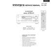
DTR-6.5
Confirmation of protection circuit
1. Confirmation of speaker relay
Confirm that the speaker relays turn ON approximately 5 seconds after the power switch is turned ON. Confirm that the speaker relays turn OFF immediately after the power switch is turned OFF.
2. How to enter Test Mode
1. To enter a test mode (Test 1 to 4), when the unit is turned on, hold down "CD" + "DISPLAY" buttons and then press "STANDBY/ON" button. 2. Press the respective designated buttons and make sure that your target mode starts. Left arrow key Right arrow key
Zone 2
Standby
Mode Test-1 Test-2 Test-3 Test-4
Button to be pressed "DVD" "VIDEO 1" "VIDEO 2" "VIDEO 3"
Message to be shown on the Front display "Test-1-00" "Test-2-00" "TUNER 82" "Test-4-00"
To move to the next step, press the right arrow key. When you enter Test-3, it is necessary to press this button once to see "Test-3-00" is shown. To move to the previous step, press the left arrow key. To exit, press "STANDBY/ON" button.
3.Confirmation of protection circuit
Check of Voltage detection 1. Enter Test-4 mode. 2. Press and release the right arrow key repeatedly until "TEST-4-21" is shown on the Front display. 3. See your unit automatically start to check each channel. During the check, the message on the display is changing as follows: Channel 1st Message 2nd Message FL+ TEST-4-21 Protect OK FR- TEST-4-22 Protect OK C+ TEST-4-23 Protect OK SL- TEST-4-24 Protect OK SR+ TEST-4-25 Protect OK SBL- TEST-4-26 Protect OK SBR+ TEST-4-27 Protect OK When the whole check is completed, "TEST-4-35" is shown. 4. Exit from the test mode. Check of Current detection 1. Enter Test-4 mode. 2. Press and release the right arrow key repeatedly until "TEST-4-35" is shown on the Front display. 3. Connect a 3 ohm hollow resistor to a speaker terminal for each channel and make sure that the speaker relay would not cut off. 4. Connect a 1.5 ohm hollow resistor to a speaker terminal for each channel and make sure that the speaker relay would cut off. 5. Exit from the test mode.
|
|
|
> |
|
|
Parse Time: 0.248 - Number of Queries: 108 - Query Time: 0.047