|
|
|
Categories
|
|
Information
|
|
Featured Product
|
|
|
 |
|
|
There are currently no product reviews.
 ;
Exactly what was needed to assess the product - excellent value and great service
 ;
Nice to have the service manual for the Sony DCR-TRV345E now. The document is of excellent quality.
;
MACKIE HR824 26 pages English-only Service Manual contains:
1) HR824 technical overview with the description of front and rear panel switches.
2) HR824 specs
3) Block Diagram
4) Wiring Diagram
5) Packaging management
6) Spare part & final assembly list (for PCB rev A and B) + exploded view
7) Test Procedures (where, how to measure voltage...) including Test Point diagram on the PCB.
8) IC and Transistor charts.
Excellent guide: very clear, good scan quality enabling us to print readable diagram :-)
Note:
Mackie HR824 make extensive use of surface mount devices (SMD). Service on the HR824 must
only be undertaken by experienced service technicians with the right tools, experience and patience to perform surface mount rework when needed.
;
This Service manual is very well scanned and its clean to read, no any anti-theft words that un-english could understand. I got my CCD600 working with this manual and it´s clear shematics :)
;
I was very pleased with the service provided and was surprised at how good the quality was of the manual. I thought it may be a third generation copy or so, but it is as good as the websites that charge 3 times this much. I repair some electronics for family and friends without charge, so this is perfect for me. Thank you very much.
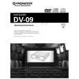
DV-09, DV-S9
Loading Mechanism Assy
Remove the tray panel after the tray opened.
Hold the DVD MAIN Assy on the MAIN SHIELD(lower).
Turn the short SW to ON position(outside)
OUTSIDE (Short position) Short SW
Turn the short SW to ON position(outside) after the PICK UP Assy moved most outside.
Remove the DVD MAIN Assy .
Remove the MAIN SHIELD(lower).
Remove the Mechanism Assy after the tray closed.
LOADING MECHANISM Assy
Assemble DOOR SUPPORT ASSY
1. Set the Gear Box to the Front Panel with condition like a indicated figure. 2. Set the door support block to the Front Panel with the Door Support opened most outside.
unengaged gear DRIVE GEAR A
lacked gear Fitting Mark () Turn clockwise
DRIVE GEAR B Fitting Mark () DRIVE GEAR D DRIVE GEAR C
NOTE: ÷ If it is hard to assemble, remove the Door Spring B. ÷ It is necessary to set precisely, if the gear is not engaged, the tray will touch the door .
SWITCH ARM
77
|
|
|
> |
|
|
Parse Time: 0.217 - Number of Queries: 103 - Query Time: 0.049