|
|
|
Categories
|
|
Information
|
|
Featured Product
|
|
|
 |
|
|
There are currently no product reviews.
 ;
Great price, Quick delivery, the document was very usefull A+++++++++++++++
;
This service Manual for my JVC AV29BF10EES is very helful. Everything is show in detailed diagrams!!!! If you need really good source of information for this type JVC you are on the right place. I am satisfied and very glad for this excellent book. Thank you.
;
Great service, great value like always!!!
Some of the writing is a bit blur but all is usable.
A+++++++++++++++++
;
Great service manua!
Always great value and fast service A++++++++++++++++++
;
Excellent Service manual, good quality scans, quick service and very good value. Well reccomended ! All good.
HCD-DX50/RG80
Note : Clear RF signal waveform means that the shape � � � can be clearly distinguished at the center of the waveform.
Adjustment Location: [BD BOARD] (Conductor Side)
RF signal waveform VOLT/DIV : 200mV TIME/DIV : 500ns
level : 0.65 ±0.15Vp-p (RFDC) 1.1 ±0.4Vp-p (RFAC)
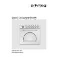
E-F Balance (1 Track jump) Check
BD board TP(TEO) TP(DVC) oscilloscope
TP (DVC) TP (RFAC) 15 1 IC103 16 30 TP (FEO) TP TP (TEO) (FEI)
21 20
40 41
IC101
1 80
Procedure : 1. Connect an oscilloscope to TP (TEO) and TP (DVC). 2. Turn Power switch on. 3. Load a disc (LUV-P01) and playback the number nine track. 4. Press the gG button. (Becomes the 1 track jump mode.) 5. Confirm that the level B and A (DC voltage) on the oscilloscope waveform.
1 track jump waveform center of waveform B A (DC voltage) DVC level=1.0 ±0.5Vp-p symmetry
TP (RFDC)
60 61
RV101
6. Adjust RV101 on the BD board so that the center of waveform becomes the same voltage of DVC. (i.e. A=0V)
18
|
|
|
> |
|
|
Parse Time: 0.168 - Number of Queries: 127 - Query Time: 0.041