|
|
|
Categories
|
|
Information
|
|
Featured Product
|
|
|
 |
|
|
There are currently no product reviews.
 ;
Yes thank you i got the file i was after. There was a slight problem in my communication but it all worked out well.
A job well done.
 ;
Great manual...really saved me. The only problem is that I thought I would be able to download it directly when I paid for it but never received the download instructions until the next morning. The board trace pages were somewhat light also: really need to turn up the contrast on the printer before printing them. The schematic page was great; very clear! Well worth the money.
;
I've been in the electronic business for a long time. I used to buy Sam's Photofact for my needs which intailed having to go to the store and paying about $20 for a package of 3 different units so I was forced to buy more than I needed just to get one.
Owner manual is just at your keyboard and the information is almost instantansouly and the cost is very reasonable. Easy to print out if needed or simply read off of the screen. The larger the screen the better for obvious reasons.
;
Very good manual, at a very good price. Received in a timely manner
;
Only thу cover has poor quality, internal material has excellent quality - exactly what I needed
Thanks!
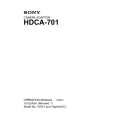
1-7. Replacement of Main Parts
1-7-2. Replacement of 50-pin connector
1. Loosen the three screws and open the outside panel. 2. Release the locks of CN501 and CN502 on the MB851 board and pull out the flexible card wires. (Refer to Section 1-7-3.)
CN501 CN502 Flexible card wires Screws
4. Remove the two slot-head screws and the two screws (M2 x 3) and remove 50-pin connector. n Do not lose the nuts on both sides of the 50-pin connector.
50-pin bracket
M2 x 3
Slot-head screws N2, TYPE2
50-pin connector N2, TYPE2
5. Desolder from the CN-1556 board and remove the 50pin connector. 6. Solder the new 50-pin connector on the CN-1556 board.
MB-851 board
50 spots
Outside panel Screw
50-pin connector
3. Remove the four screws and remove the 50 PIF assembly together with the flexible card wire from the unit.
M2.6 x 5 M2.6 x 5
CN-1556 board
50 PIF assembly
7. Install the 50 PIF assembly in the reverse order of steps 3 through 6. n When installing the 50 PIF assembly, pull the two flexible card wires toward the outside panel from the clearance between the unit and the MB-851 board. 8. Connect the two flexible card wires to CN501 and CN502 on the MB-851 board. (Refer to Section 1-7-3.) 1-7 (E)
HDCA-701 MM
|
|
|
> |
|