|
There are currently no product reviews.
 ;
Very complete and well reading drawings. Documentation is essential for successful repairs.Good documentation, with all that is necessary. This manual was what I was waiting with all the information necessary for the repairing I need it for. You must buy it if you want to do repairs or simply understand how it works.
 ;
Excellent service manual includes everything is need to repair this radio-caseete, how to disassemble, wiring diagram, all , waiting time until the download was only a few hours. I'm going to buy service manuals from here, are cheap and very good.Thank you.
;
Good service manual,i saved from scrapping this deck,is now fully functional.Thanks.
;
Found this to be the manual included with the original packinging, was helpfull but did not give any detailed repair instructions.
;
Complete service manual, was very helpful in repairing this tapedeck.Thanks.
Touch current check
(After completing the work, measure touch current to prevent an electric shock.) �Plug the AC cord directly into the AC outlet. Do not use an isolation transformer for this check..
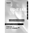
�Connect a measuring network for touch currents between each exposed metallic part on the set and a good earth ground such as a water pipe, as shown in Figure D.1
�The potential at any point(TOUCH CURRENT) expressed as voltage U1 and U2 does not exceed the following value:
The part or contact of a TERMINAL is not HAZARDOUS LIVE if: a) the open-circuit voltage does not exceed 35 V (peak) a.c or 60 V d.c., or,if a)is not met, b) the measurement of the TOUCH-CURRENT shall be carried out in accordance with IEC 60990, with the measuring network described in annex D of this standard. The TOUCH CURRENT expressed as voltages U1 and U2, does not exceed the following values: - for a.c.:U1= 35 V(peak)and U2=0.35 V (perk); - for d.c.:U1= 1,0 V, NOTE 5 -The limit values of U2=0.35 V (peak) for a.c. and U1=1.0 V for d.c. correspond, to the values 0,7mA (peak) a.c. and 2,0 mA 2,0mA d.c. The limit value U1= 35 V (peak) for a.c. corresponds to the value 70mA (peak) a.c. for frequencies greater than 100 kHz.
Annex D (normative) Measuring network for TOUCH CURRENTS
A
Test TERMINALS
Rs= 1 500Ω
Cs= 0.22uF 10kΩ
B
Rb = 500Ω
U1
0.022uF
V
U 2 (V)
IEC 802/96
Resistance values in ohms(Ω) V: Voltmeter or oscilloscope (r.m.s or peak reading) Input resistance: �1 MΩ Input capacitance: � 200 pF Frequency range: 15 Hz to 1 MHz and d.c. respectively NOTE-Appropriate measures should be taken to obtain the correct value in case of non-sinusoidal waveforms. The measuring instrument is calibrated by comparing the frequency factor of U2 with the solid line in figure F.2 of IEC 60990 at various frequencies. A calibration curve is constructed showing the deviation of U2 from the ideal curve as a function of frequency. TOUCH CURRENT=U2/500(peak value)
Fig.D.1
|