|
|
|
Categories
|
|
Information
|
|
Featured Product
|
|
|
 |
|
|
There are currently no product reviews.
 ;
It was very usefull, it is clear the quality is super, the price I paid is very afordable.
Generally speaking Iam very happy with this company.
;
The manual was exactly what I needed, Good quality scans too. superb.
;
I am so happy found this site as it consists of so many Manuls and easy to aquire. This onei s exactly what I wanted and much more as it has info on not only how to use the tuner but how to repair it as well. I will come here 1st before purchasing else where! Thanks owner-manual.com!
;
Top class product, I printed it out on A3 paper and it is clear and very easy to follow.
Cheaper than buying a new radio!
;
is part of the manual is very useful for repairing
Here are circuit diagrams
if there is damage, I recommend using this part of the
a complete list of circuit boards and components
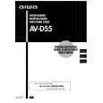
ELECTRICAL ADJUSTMENT
TUNER C.B
FFE801
3
6
IC BLOCK DIAGRAM IC, BU4094BCF
TP6
4
L772 TP1 L981
L771
TP3 TP2 1/3 TP4
IC771 TP5
4
< TUNER SECTION >
1. Clock Frequency Check Settings: � Test point: TP2 (CLK IC771 pin30) Method: Set to AM 1710kHz and check that the test point becomes 2160kHz±45Hz. 2. AM VT Check Settings: � Test point: TP1 (VT) Method: Set to AM 1710kHz and check that the test point is less than 8.5V. Then set to AM 530kHz and check that the test point is more than 0.6V. 3. AM IF Adjustment Settings: � Test point: TP5, TP6 L772 .............................................. 450kHz 4. AM Tracking Adjustment Settings: � Test point: TP5, TP6 � Adjustment location: L981 (1/3) Method: Set to AM 999kHz and adjust L981 so that the test point becomes maximum. 5. FM VT Check Settings: � Test point: TP1 (VT) Method: Set to FM 87.5MHz, 108.0MHz and check that the test point is more than 0.5V (87.5MHz) and less than 8.0V (108.0MHz). 6. DC Balance/Mono Distortion Adjustment Settings: � Test point: TP3, TP4 � Adjustment location: L771 � Input level: 60dB Method: Set to FM 98.0MHz and adjust L771 so that the voltage between TP3 and TP4 becomes 0V±0.04V. Next, check that the distortion is less than 1.3%.
IC, M62431FP
PRACTICAL SERVICE FIGURE
< TUNER SECTION >
<FM SECTION> Signal to noise ratio: Distortion: (Input: 60dB) Stereo separation: Intermediate frequency: <AM SECTION> Sensitivity: (S/N 20dB) Signal to noise ratio: (Input: 74dB) Distortion: Intermediate frequency: More than 62dB (at 98.0MHz) Less than 2.0% (at 98.0MHz) More than 22dB (at 98.0MHz) 10.7MHz
Less than 60dB (at 600kHz) Less than 58dB (at 1000/1400kHz) More than 36dB (at 1000kHz) Less than 1.5% (at 1000kHz) 450kHz
IC, M62439SP
35
36
 $4.99 HTD390 AIWA
Owner's Manual Complete owner's manual in digital format. The manual will be available for download as PDF file aft…
|
|
|
> |
|