|
|
|
Categories
|
|
Information
|
|
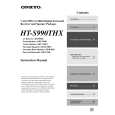
Featured Product
|
|
|
 |
|
|
There are currently no product reviews.
 ;
The manual was exact the thing that was promised. My old car stereo is working again thanks to the information supplied.
;
I PURHASED THIS PRODUCT BECAUSE I WAS HAVING PROBLEMS WITH MY CDR20 HARMAN KARDON RECORDER. WHICH I PURCHASED NEW 12 YEARS AGO. AFTER REVIEWING THE MANUAL, I WAS ABLE TO ADJUST THE TENSIONER IN THE SYSTEM. WORKS LIKE A CHAMP!.
SAVED ME AT LEAST 100.00 WHICH WAS WHAT A SERVICE REPAIR STATION WANTED. GREAT MANUAL EASY TO READ. SPECIALLY AFTER I PRINTED THE PAGES WHICH DEALT WITH MY RECORDER. THANKS A LOT!!!!!!!!
 ;
You can fully trust on this one!
All the schematics are very crear an in one piece per page
;
I have never bought a service manual which is as competely readable as this althogh it was a scanned pdf. Thank you for this succesful manual also cheaper than other sites.
;
Thanks for a very good and readable servicemanual. Just what I needed as a "dinosaur technician". I really recommmend this site and will come back.
Åsbjörn
TX-SR574 IC BLOCK DIAGRAM AND TERMINAL DESCRIPTIONS-17
Q4001 : ADV7183 (Advanced Video Decoder with 10-Bit ADC and Component Input Support)-2/3
TERMINAL DESCRIPTION (1/2)
Pin 1 Mnemonic VS/VACTIVE Input/Output O Function VS or Vertical Sync. A dual-function pin, (OM_SEL[1:0] = 0, 0) is an output signal that indicates a vertical sync with respect to the YUV pixel data. The active period of this signal is six lines of video long. The polarity of the VS signal is controlled by the PVS bit. VACTIVE (OM_SEL[1:0] = 1, 0 or 0, 1) is an output signal that is active during the active/viewable period of a video field. The polarity of VACTIVE is controlled by PVS bit. HS or Horizontal Sync. A dual-function pin, (OM_SEL[1:0] = 0, 0) is a programmable horizontal sync output signal. The rising and falling edges can be controlled by HSB[9:0] and HSE[9:0] in steps of 2 LLC1. The polarity of the HS signal is controlled by the PHS bit. HACTIVE (OM_SEL[1:0]= 1, 0 or 0, 1) is an output signal that is active during the active/viewable period of a video line. The active portion of a video line is programmable on the ADV7183. The polarity of HACTIVE is controlled by PHS bit. Digital I/O Ground Digital I/O Supply Voltage (3.3 V) Video Pixel Output Port. 8-bit multiplexed YCrCb pixel port (P15-P8), 16-bit YCrCb pixel port (P15-P8 = Y and P7-P0 = Cb,Cr). Ground for Digital Supply Digital Supply Voltage (3.3 V) Almost Full Flag. A FIFO control signal indicating when the FIFO has reached the almost full margin set by the user (use FFM[4:0]). The polarity of this signal is controlled by the PFF bit. Half Full Flag. A multifunction pin, (OM_SEL[1:0] = 1, 0) is a FIFO control signal that indicates when the FIFO is half full. The QCLK (OM_SEL[1:0] = 0, 1) pin function is a qualified pixel output clock when using FIFO SCAPI mode. The GL (OM_SEL[1:0] = 0, 0) function (Genlock output) is a signal that contains a serial stream of data that contains information for locking the subcarrier frequency. The polarity of HFF signal is controlled by PFF bit. Almost Empty Flag. A FIFO control signal, it indicates when the FIFO has reached the almost empty margin set by the user (use FFM[4:0]). The polarity of this signal is controlled by PFF bit. Asynchronous FIFO Clock. This asynchronous clock is used to output data onto the P19-P0 bus and other control signals. General-Purpose Outputs controlled via I 2 C Clock Reference Output. This is a clock qualifier distributed by the internal CGC for a data rate of LLC2. The polarity of LLCREF is controlled by the PLLCREF bit. Line-Locked Clock System Output Clock/2 (13.5 MHz) Line-Locked Clock System Output Clock. A dual-function pin (27 MHz or a FIFO output clock ranging from 20 MHz to 35 MHz. Second terminal for crystal oscillator; not connected if external clock source is used. Input terminal for 27MHz crystal oscillator or connection for external oscillator with CMOS-compatible square wave clock signal Power-Down Enable. A logical low will place part in a power-down status. This pin is used for the External Loop Filter that is required for the LLC PLL. 5%)
2
HS/HACTIVE
O
3, 14 4, 15
DVSSIO DVDDIO
G P O G P O
5-8, 19-24, P15-P0 32, 33, 73-76 9, 31, 71 10, 30, 72 11 DVSS1-3 DVDD1-3 AFF
12
HFF/QCLK/GL
I/O
13
AEF
O
16
CLKIN
I O O
17, 18, 34, 35 GPO[3:0] 25 LLCREF
26 27 28 29 36 37 38 39
LLC2 LLC1/PCLK XTAL1 XTAL PWRDN ELPF PVDD PVSS
O O O I I I P G
|
|
|
> |
|