|
|
|
Who's Online
There currently are 5919 guests online. |
|
Categories
|
|
Information
|
|
Featured Product
|
|
|
 |
|
|
There are currently no product reviews.
 ;
Excellant, finally this is want I need and searching for The service manual is fantastic and thank you to owner-manuals.com and its service. Price is reasonable. It's a bit slow on my end in downloading but manage to receive the whole manual without a break. once again, thanks.
;
Very good scanning quality. All schematics are very legible. Worth every cent !
;
Excellent quality, very quick download turnaround, will definately use again.
 ;
This is a awesome quality scan of the original Service Manual for Technics 8099.
Contains the circuit diagram, PCB layout, adjust/tune instructions as well.
Since this is my first buy here, i'm really glad! This site do works as intended/described, it's definitely not scam!
Мои рекомендации! Все мануалы настоящие!
;
Good Quality of the File.
You get the normal manual is incudet.
ICF-CD863/CD863L
Adjustment Location:
� MAIN BOARD (Component Side) �
AUTO BRIGHTNESS ADJUSTMENT Connecting:
digital voltmeter LCD board TP (DIMMER) TP (GND) 100 k � + �
CD SECTION
CD section adjustments are done automatically in this set. In case of operation check, confirm that focus bias.
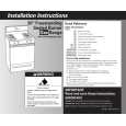
FOCUS BIAS CHECK
1. Connect the oscilloscope to TP (RF) and TP (GND) on the CD board. 2. Insert the disc (YEDS-18). (Part No. : 3-702-101-01) 3. Press the u (CD) button. 4. Confirm that the oscilloscope waveform is as shown in the figure below. (eye pattern) A good eye pattern means that the diamond shape (�) in the center of the waveform can be clearly distinguished. � RF signal reference waveform (eye pattern)
VOLT/DIV: 0.2 V (with the 10: 1 probe in use.) TIME/DIV: 500 ns
CT4 LW VCO Voltage Adjustment (CD863L) L4 AM (MW) VCO Voltage Adjustment RV1 FM Stereo Adjustment L1 FM RF CT2 Tracking Adjustment
}
T1 AM IF Adjustment
1. Set to power off state. 2. Connect a digital voltmeter to TP (DIMMER) and TP (GND) on the LCD board and confirm that the voltage is 0 V. 3. Turn on the power. 4. Connect the digital voltmeter to TP (DIMMER) and TP (GND) on the LCD board and adjust RV401 so that the voltage becomes 1.5 ± 0.05 V. 5. Turn off the power. 6. Applied sufficient light to IC403 (brightness sensor) on the DIMMER board and confirm that the voltage is 3.3 ± 0.3 V. 7. Short the BP404. Adjustment Location: � LCD BOARD (Component Side) �
0.8 ± 0.2 Vp-p
L3-1 AM (MW) Tracking CT2 Adjustment
}
L3-2 LW Tracking Adjustment CT3 (CD863L)
}
When observing the eye pattern, set the oscilloscope for AC range and raise vertical sensitivity.
Adjustment Location:
� MAIN BOARD (Conductor Side) �
TP (FM IN)
RV401 Auto Brightness Adjustment
� CD BOARD (Conductor Side) �
TP (GND) TP (VT) TP (FM ST)
IC701
� LCD BOARD (Conductor Side) �
TP (GND)
TP (RADIO B+)
TP (GND)
TP (RF)
1 4 CN303
TP (DIMMER)
� DIMMER BOARD (Conductor Side) �
IC403
13
13
|
|
|
> |
|