|
|
|
Categories
|
|
Information
|
|
Featured Product
|
|
|
 |
|
|
There are currently no product reviews.
 ;
It`s not your fault tear down is rather incomplete. It doesn`t have complete instructions as to deconstruction for repair.
 ;
THANK YOU FOR A GOOD TRANSACTION, NICE COPY, CLEAR
;
Very Good! All the diagram are easy to read, and its complete.
;
This was an excellent source of detailed assembly information on a device which is at least 12 years old. A very lucky find, coupled with great service.
;
Excellent Service Manual and best price on the Internet. This Service Manual covers everything you could ever need including full circuit schematics, component layout diagrams, stripdown procedure and full parts list/breakdown. I needed this to carry out a modification to one of these headunits and this manual covered everything I needed. Fast delivery, processed within a few hours.
SECTION 3 SET-UP ADJUSTMENTS
3-1. SCREEN VOLTAGE ADJUSTMENT (ROUGH ALIGNMENT)
1. Receive the Monoscope signal. 2. Set 50% BRIGHTNESS and minimum PICTURE. 3. Turn the red VR on the FOCUS block all the way to the left and then gradually turn it to the right until the point where you can see the retrace line. 4. Next gradually turn it to the left to the position where the retrace line disappears.
KP-41S5/41S5B/41S5G/ 41S5K/41S5R/41S5U
RM-862
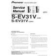
3-3. SCREEN (G2) ADJUSTMENT
1. 2. 3. 4. Connect jig (A) to 200V. In TP732, CG Board. Connect jig (B) to GND. In TP733, CG Board. Select with Power ON, VIDEO mode without signals. Connect jig (C) to the TP701 (K.CR), TP731 (K:CG), or TP761 (K.CB) of CR, CG, and CB Board. 5. Adjust R, G, and B screen voltage to until retrace line just appears with screen VR on the Focus block
KR-KG-KB (C)
2.2k / 3W x2
R
G SCREEN
B
5.6k / 3W
(B) GND
2.2k / 3W
B
R
G FOCUS
(A) 200V
Fig. 3-3
FOCUS block Fig. 3-1
3-4. FOCUS VR ADJUSTMENT
1. Set in service mode. 2. Use GH (GSEL) on the service mode menu to shown only the green color. 3. Press the Commander Menu button (convergence) and output the test signal (crosshach). 4. Rotate the green VR on the FOCUS block and align to obtain the optimal focus point. 5. Use GH (GSEL) from the service mode menu to set to green and red. 6. Output the test signal and rotate the red VR to obtain the optimum focus at the point where the red and green spots overlap. 7. Use BH (BSEL) from the service mode menu to set to red and blue. 8. Output the test signal and rotate the blue VR aligning to obtain the optimum focus at the point where the blue and green spots overlap.
3-2. FOCUS LENS ADJUSTMENT
1. Loose the lens screw. 2. Set in service mode. 3. Use GH (GSEL) on the service mode menu to shown only the green color. 4. Press the Commander Menu button and select TEST MENU and CONVERGENCE to display the test signal (crosshatch) on the screen. 5. Rotate the green lens and align with the optimal focus point from the test signal. 6. Use GH (GSEL) from the service mode menu to set to green and red. 7. Output the test signal and rotate the red lens to obtain the optimum focus at the point where the red and green spots overlap. 8. Use BH (BSEL) from the service mode menu to set to red and blue. 9. Output the test signal and rotate the blue lens to obtain the optimum focus at the point where the blue and red spots overlap. 10. Tighten the lens screw.
Scanning line visible. Scanning line visible.
A Minimize both AA and B. A Minimize both and B.
Lens Fig. 3-4 Test signal Fig. 3-2
B B
Fig. 3-5
� 19 �
|
|
|
> |
|