|
|
|
Categories
|
|
Information
|
|
Featured Product
|
|
|
 |
|
|
There are currently no product reviews.
 ;
Nice manual. Clear copy and very rare, to boot. Great price, too!
 ;
Excellent service manual. Complete service info. with schematics, step-by-step instructions and illustrations. Well worth the price!
;
Great product, helped me to restore vintage walkman cassette.
Just some pictures could be little bit more sharp and contrast
Thank you
;
I love older radio's and the service manuals that are sometimes hard to find. Was able to find a manual quite easily on this site.
;
Thank you for your shop manual! Your help was very useful - the device is repaired! Once again - Thank you! I wish you a successful business! Edward (Russia).
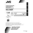
Item 1. Head azimuth adjustment
Conditions Test tape: SCC-1659 VT703 (10kHz)
Adjustment and Confirmation methods Head height adjustment Adjust the azimuth directly. When you adjust the height using a mirror tape, remove the cassette housing from the mechanism chassis. After installing the cassette housing, perform the azimuth adjustment. (1) Load the SCC-1659 mirror tape. Adjust with height adjustment screw A and azimuth adjustment screw B so that line A of the mirror tape runs in the center between Lch and Rch in the reverse play mode. (2) After switching from REV to FWD then to REV, check that the head position set in procedure 1 is not changed. (If the position has shifted, adjust again and check.) (3) Adjust with azimuth adjustment screw B so that line B of the mirror tape runs in the center between Lch and Rch in the forward play mode.
S.Values
Adjust
A line
Head shield The head is at low position during.
B line
Head shield The head is at High position during REV. Output level: Maximum PBHead FWD Adj B
Test tape: VT724 (1kHz) VT703 (10kHz) VT721 (315Hz)
Head azimuth adjustment (1) Load VT724 (1kHz) and play it back in the reverse play mode. Set the Rch output level to max. (2) Load VT703 (10kHz) and play it back in the forward play mode. Adjust the Rch and Lch output levels to max, with azimuth adjustment screw B. In this case, the phase difference should be within 45 . (3) Engage the reverse mode and adjust the output level to max, with azimuth adjustment screw C.(The phase difference should be 45 or more.) (4) When switching between forward and reverse modes, the difference between channels should be within 3dB. (Between FWD L and R, REV L and R.) (5) When VT721 (315Hz) is played back, the level difference between channels should be within 1.5dB.
REV Adj C
HEIGHT Adj A
(0 )
phase
(45 )
2. Tape speed Test tape: and wow flut- VT712 (3kHz) ter confirmation 3. Play back frequency response confirmation Test tape: VT724 (1kHz) VT739 (63Hz / 1kHz / 10kHz)
(1) Check to see if the reading of the F, counter / wow flutter meter is within 3015Hz to 3045Hz (FWD/ REV), and less than 0.35% (JIS RMS). (2) In case of out of specification, adjust the motor with a built-in volume resistor.
Tape speed: 3015Hz to 3045Hz Wow flutter: less than 0.35%
Built-in volume resistor
(1) Play test tape VT724, and set the volume position at Speaker out 2V. 1kHz / 63Hz: 0 ±3dB (2) Play test tape VT739 and confirm.1kHz / 10kHz: -1 1kHz / 10kHz: -1 ±3dB ±3dB,1kHz / 63Hz: 0 ±3dB, (3) When 10kHz is out of specification, it will be necessary to read adjust the azimuth.
The tuner section is of an adjustment-freedesign. In case the tuner is in trouble, replace the tuner pack.
(No.49855)1-23
|
|
|
> |
|