|
|
|
Who's Online
There currently are 5961 guests and
2 members online. |
|
Categories
|
|
Information
|
|
Featured Product
|
|
|
 |
|
|
There are currently no product reviews.
 ;
Do a quick order, scan quality is high.
I recommend to all!
;
This manual is perfect! Just what I needed. Thanks!
;
This manual was very clear and complete, the prices can't be beat, great to have older manuals available!
 ;
Doubted for buy this manual as it is my first order here and at not have cover image, I assumed would haven't. However, within 24 hs, already possessed the link to download it. The manual are scanned correctly and have all what is needed. Includes adjustments and diagrams of all circuits. Very satisfied.
;
Really good quality, аll readable.! Wonderful work shop. I recommend to all!
KV-20FS12/20FV12/21FE12/A/C/21FM12/21FV12/C
2-4. PICTURE TUBE REMOVAL
WARNING: BEFORE REMOVING THE ANODE CAP High voltage remains in the CRT even after the power is disconnected. To avoid electric shock, discharge CRT before attempting to remove the anode cap. Short between anode and CRT coated earth ground strap.
10
1
2
9 8 7 6
3
Coated Earth Ground Strap
5
4 1. 2. 3. 4. 5. Discharge the anode of the CRT and remove the anode cap. Unplug all interconnecting leads from the deflection yoke, neck assembly, degaussing coils and CRT grounding strap. Remove the CB Board from the CRT. Remove the chassis assembly. Loosen the neck assembly fixing screw and remove. 6. 7. 8. Loosen the deflection yoke fixing screw and remove. Place the set with the CRT face down on a cushion and remove the degaussing coil holders. Remove the degaussing coils.
9. Remove the CRT grounding strap and spring tentioners. 10. Unscrew the four CRT fixing screws [located on each CRT corner] and remove the CRT [Take care not to handle the CRT by the neck].
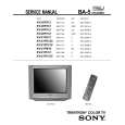
ANODE CAP REMOVAL
WARNING: High voltage remains in the CRT even after the power is disconnected. To avoid electrical shock, discharge the CRT before attempting to remove the anode cap. Short between anode and coated earth ground strap of CRT. NOTE: After removing the anode, short circuit the anode of the picture tube and the anode cap to either the metal chassis, CRT shield, or carbon painted on the CRT.
REMOVAL PROCEDURES
c b
a
Anode Button
1
Turn up one side of the rubber cap in the direction indicated by arrow a .
2
Use your thumb to pull the rubber cap firmly in the direction indicated by arrow b .
3
HOW TO HANDLE AN ANODE CAP
1 2
When one side of the rubber cap separates from the anode button, the anode cap can be removed by turning the rubber cap and pulling it in the direction of arrow c .
Do not use sharp objects which may cause damage to the surface of the anode cap. To avoid damaging the anode cap, do not squeeze the rubber covering too hard. A material fitting called a shatter-hook terminal is built into the rubber. Do not force turn the foot of the rubber cover. This may cause the shatter-hook terminal to protrude and damage the rubber.
3
� 14 �
|
|
|
> |
|