|
|
|
Categories
|
|
Information
|
|
Featured Product
|
|
|
 |
|
|
There are currently no product reviews.
 ;
Perfect source for service manuals: fast and professional transaction; high quality, perfect readable and largely scaleable PDF; complete schemes, diagrams and spare part list. Tnx a lot, cu again!!!!
;
I got your link from a friend and I must say that I am really satisfied with your service. Specially this B&O manual I didn't find anywhere on the web... but you could deliver it :-) . You deliver very fast and the copy is of good quality. So your webpage is bookmarked. Thanks
;
This was the Sony CCU-500A Service manual I was looking for.
The price was reasonable.
The permission to download was quck.
I will use Owner-Manual.com for all my manual needs.
;
Excellent printing quality.
A complete and very usefull service manual with all details.
GREAT SERVICE AT VERY LOW PRICE!
A+++++++++++++++++++++++++
;
Excellent printing quality.
A complete and very usefull service manual with all details.
GREAT SERVICE AT VERY LOW PRICE!
A+++++++++++++++++++++++++
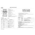
2-5. Boards Replacement
2-5-4. PSW-61 Board
n When the PSW-61 board is replaced, replace a whole harness (H61) that is connected to PSW-61 board. 1. Disconnect the power cords from the rear panel. 2. Remove the cover. (Refer to Section 2-2-2.) 3. Remove the front panel (lower) and ornamental panel A. (Refer to Section 2-2-1.) 4. Open the front panel A. (Refer to Section 2-4-2.) 5. Remove the power supply units. (Refer to Section 2-42.) When there is one power supply, remove the blank panel. (Refer to Section 2-5-2.) 6. Remove the all HDD units. (Refer to Section 2-4-3.) 7. Remove the front stay. (Refer to Section 2-5-2.) 8. Remove the two power guides. (Refer to Section 2-52.) 9. Remove the IF positioning bracket. (Refer to Section 10. 11. 12. 2-5-2.) Unstick the filter from the front panel A. (Refer to Section 2-4-5.) Remove the LCD case lid. (Refer to Section 2-5-3.) Disconnect the two connectors (CN1, CN4) of the harness connected to the DP-269 board. (Refer to Section 2-5-3.) Remove the DP-269 board. (Refer to Section 2-5-3.) Remove the cable clamp. (Refer to Section 2-5-3.) Remove the PSW-61 board from the front panel A. (Refer to Section 2-5-3.) Cut the two harness clampers.
17. Disconnect the two connectors (CN1, CN10) of the harness connected to the AC-188 board . 18. Remove the all optional boards. (Refer to Section 2-55.) 19. Remove the four screws (BVTT 3x6) and two screws (PSW 3x6). 20. Pull out the noise filters until the harness is viewed. n Be sure not to pull out the harness connected to the noise filter. 21. Remove the four connectors of the harness connected to the noise filters. 22. Remove the PSW-61 board connected to the harness (H61).
BVTT 3x6
Noise filters
CN1 PSW 3x6
CN10
13. 14. 15. 16.
AC-188 board PSW-61 board
23. For installation, perform the removal procedures in reverse order. n Use the commercially available harness clamper .
PSW-61 board Harness clampers
MAV-70
2-21 (E)
|
|
|
> |
|
|
Parse Time: 0.202 - Number of Queries: 123 - Query Time: 0.045