|
|
|
Categories
|
|
Information
|
|
Featured Product
|
|
|
 |
|
|
There are currently no product reviews.
 ;
Excellent printing quality.
A complete and very usefull service manual with all details.
GREAT SERVICE AT VERY LOW PRICE!
A++
;
Best help everywhere i got from here. My audio medicinman was happy to get this manual from me. So he could repair my pioneer perfectly. Thanks
R O
;
It was very usefull, it is clear the quality is super, the price I paid is very afordable.
Generally speaking Iam very happy with this company.
;
The manual was exactly what I needed, Good quality scans too. superb.
;
I am so happy found this site as it consists of so many Manuls and easy to aquire. This onei s exactly what I wanted and much more as it has info on not only how to use the tuner but how to repair it as well. I will come here 1st before purchasing else where! Thanks owner-manual.com!
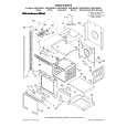
MC-CG973-00
3.3.
3.3.1.
POWER NOZZLE MOTOR
Specifications
1. 120V., 60Hz. 2. Amps 2.0/2.7 (max.) at 18,000/14,550 R.P.M. 3. Watts 225/298 (max.) at 18,000/14,550 R.P.M. 3. Line up front of cover and base. 4. Rest cover on front edge of base as shown. 4. Torque 55/100 Nm at 18,000/14,550 R.P.M.
3.3.2.
Motor Replacement
1. Remove Power Nozzle cover, nozzle cover and agitator assembly (see BELT REMOVAL. 2. Remove two (2) motor bridge screws. Lift out bridge and motor. NOTE: Observe routing of motor wires and all other wiring before removing motor. 5. Rotate cover back. 3. Hook a finger under the center of the overload protector and lift to free it from the retaining tabs. Remove the overload protector wire terminals. Check continuity by depressing the button completely. When the button is released there should be continuity between the two poles when checked. If all components and items in the troubleshooting guide have been checked and the overload protector continues to trip, it should be replaced. 4. Insert a flat screwdriver blade between the indicator block assembly and the plastic retainer for the four (4) wires. Pry up and out to free the indicator block assembly from the retaining tabs.
6. Press cover firmly until side and rear tabs snap into place. 7. Replace two (2) cover screws.
5. Unscrew wire nuts to free motor lead wires.
6. Install new motor. Assure motor is fully seated on all four (4) front and rear base supports. Rear motor housing flange should be in slot of base support.
12
|
|
|
> |
|