|
|
|
Categories
|
|
Information
|
|
Featured Product
|
|
|
 |
|
|
There are currently no product reviews.
 ;
Complete service manual, was very helpful in repairing this tapedeck.Thanks.
;
The service manual was a copy of the original from Wirlpool. The quality was good, all neccecary information was available including the service-codenumbers, so I could order the right part to be replaced for repair.
Downloding was no probem after the payment.
Thanks for the service!
;
Good,readable manual. I found other manuals that were not readable when it came to part ID, but the one downloaded from owner-manual.com was better than expected. I will do buisness with owner-manual.com again.
;
Service Manual that I received was very helpful to me. Thank you.
;
The manual is well organized and is easy to read. The chapters are following normal way to proceed.
DISASSEMBLY INSTRUCTIONS
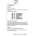
3. REMOVAL OF ANODE CAP
Read the following NOTED items before starting work. * After turning the power off there might still be a potential voltage that is very dangerous. When removing the Anode Cap, make sure to discharge the Anode Cap's potential voltage. * Do not use pliers to loosen or tighten the Anode Cap terminal, this may cause the spring to be damaged. REMOVAL 1. Follow the steps as follows to discharge the Anode Cap. (Refer to Fig. 3-1.) Connect one end of an Alligator Clip to the metal part of a flat-blade screwdriver and the other end to ground. While holding the plastic part of the insulated Screwdriver, touch the support of the Anode with the tip of the Screwdriver. A cracking noise will be heard as the voltage is discharged. 3. After one side is removed, pull in the opposite direction to remove the other. NOTE Take care not to damage the Rubber Cap. INSTALLATION 1. Clean the spot where the cap was located with a small amount of alcohol. (Refer to Fig. 3-3.) NOTE Confirm that there is no dirt, dust, etc. at the spot where the cap was located.
Location of Anode Cap
GND on the CRT
Fig. 3-3 2. Arrange the wire of the Anode Cap and make sure the wire is not twisted. 3. Turn over the Rubber Cap. (Refer to Fig. 3-4.)
Screwdriver Support Alligator Clip GND on the CRT
CRT
Fig. 3-1
Fig. 3-4 4. Insert one end of the Anode Support into the anode button, then the other as shown in Fig. 3-5.
2. Flip up the sides of the Rubber Cap in the direction of the arrow and remove one side of the support. (Refer to Fig. 3-2.) Rubber Cap
CRT Support Fig. 3-2 B3-1
CRT
Support Fig. 3-5
5. Confirm that the Support is securely connected. 6. Put on the Rubber Cap without moving any parts.
|
|
|
> |
|