|
|
|
Categories
|
|
Information
|
|
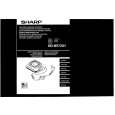
Featured Product
|
|
|
 |
|
|
There are currently no product reviews.
 ;
Quality scan of the original. All the detail necessary to troubleshoot, repair and adjust the unit. I'm sure I will be downloading more manuals in the future as the need arises.
;
Exactly as described, a Service Manual complete with the schematics and PCB layout delivered in a timely manner. Many thanks for the great service.
 ;
some of the writing is a bit blur but the part in the schmatic was great and i have fixed the machine thanks
;
Well.. I'd searched for this manual and although I found many copies online I was pleased to find your website with a well balanced pricing system and easy to search and follow links. That together with the very quick response time was just what I was looking for.. being a very impatient tech.. ;-) I had the service manual in front of me within a short time.
Bookmarked.. and you can bet I will always come here first for my service & user manuals..
best regards
Ed(Tony) Foley
G7WHK
;
I will definitely be back for more information when I need it.
MD-MS722H/MS721H
NOTES ON SCHEMATIC DIAGRAM
� Resistor: To differentiate the units of resistors, such symbol as K and M are used: the symbol K means 1000 ohm and the symbol M means 1000 kohm and the resistor without any symbol is ohm-type resistor. Besides, the one with �Fusible� is a fuse type. � Capacitor: To indicate the unit of capacitor, a symbol P is used: this symbol P means micro-micro-farad and the unit of the capacitor without such a symbol is microfarad. As to electrolytic capacitor, the expression �capacitance/withstand voltage� is used. (CH), (TH), (RH), (UJ): Temperature compensation (ML): Mylar type � The indicated voltage in each section is the one measured by Digital Multimeter between such a section and the chassis with no signal given. � Parts marked with � �( ) are important for maintaining the safety of the set. Be sure to replace these parts with specified ones for maintaining the safety and performance of the set.
REF. NO SW401 SW402 SW901 SW902 EJECT HOLD DISC IN DISC PROTECT DESCRIPTION POSITION OFF�ON OFF�ON OFF�ON OFF�ON
B (G) (3) E (S) 1
TOP VIEW TOP VIEW 2SA17457 2SC4213B 2SK2909 2SK2911 DTA114YE DTA144TE DTC144TE RN1444A TOP VIEW
C (D) (2)
TOP VIEW
1SS361
015Z5.1Y 015AZ7.5Y 1SS368 RB521S30
TOP VIEW
TOP VIEW
F1J2F
SB0209CP 1SS372
F10J2E RB491D SB10015C
Figure 35 TYPES OF TRANSISTORS AND DIODES
� 35 �
|
|
|
> |
|