|
|
|
Categories
|
|
Information
|
|
Featured Product
|
|
|
 |
|
|
There are currently no product reviews.
 ;
good scans, all is clear. all pages in order. recommended
 ;
Très-très bon site, facile, très bon prix.
Au futur besoin, je n’hésiterais à faire appel à vous.
Merci
;
This is the correct service manual of SHARP RX-100H(BK) DAT.
;
The ervice manual for my 1982 Kenwood KR-1000 receiver is great! Full detail on all circuits with part number detail. I will definately be ordering more manuals for my other vintage equipment! Order was fulfilled quickly! Very efficient ordering process! Thnaks for your help! Great site!
;
Everything in the manual was excellent except for a couple of pictures of specific areas in the unit that were a little dark. Owners Manuals re-sent the pdf file & the problem was corrected. Excellent product! George
MJ-D508
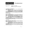
7.1.2 DISASSEMBLY Removal of the Servo Mechanism Assy
1 Remove the screw A and screw B. 2 Disconnect the connectors (CN102, CN103, CN105), open the hook of part A, and tilt the upper side of the CORE MAIN UNIT ASSY to the front. 3 Disconnect the connector (CN101) at the rear of the CORE MAIN UNIT ASSY and remove the CORE MAIN UNIT ASSY. 4 After the Carrier has been pushed in, move the Upper Slider to the rear and stop it at the position where the Under Slider starts to move.
2
CN105 Screw A
2 1
Screw B CN101 CN102
Part A
2 CN103 3
1
CORE MAIN UNIT ASSY
5 Shift part B to the position shown in the figure while raising the Under Slider. (At the same time, the Upper Slider moves to the front.) 6 Remove the Lock Plate. (One screw B)
Under Slider Upper Slider
4
Part B
Screw C
5
7 Remove the Servo Mechanism Assy.
Lock Plate
Servo Mechanism Assy
Caution for the time of installation of the servo mechanism assy
Move the MD Pick-up to the innermost circumference. The servo mechanism assembly is not installed other than the innermost circumference.
6
52
|
|
|
> |
|
|
Parse Time: 0.172 - Number of Queries: 123 - Query Time: 0.043