|
There are currently no product reviews.
 ;
I am a vintage hifi collector. No way to fix that device without the appropriate service manual...thanks to your site I got it and every thing is easier now. I got the manual right after ordering: fast cheap accurate ... thank you
;
Wonderful job clear. Qick fantastic. These people are really good. If even a problem arise they are wonderful assisting you. These scheme is so net despite this is a very old TV. Thank you for everything!!!!!!!!
;
Detailed schematic diagram, manual for professionals
;
Good service manual,exploded view,adjusment and test point locations,head alignment,mechanical checks and adjusments,all perfect.
;
Block diagram,play rec block diagram,adjusments, it's a very good well done repair manual.
MJ-D508
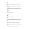
7.1.2 DISASSEMBLY Removal of the Servo Mechanism Assy
1 Remove the screw A and screw B. 2 Disconnect the connectors (CN102, CN103, CN105), open the hook of part A, and tilt the upper side of the CORE MAIN UNIT ASSY to the front. 3 Disconnect the connector (CN101) at the rear of the CORE MAIN UNIT ASSY and remove the CORE MAIN UNIT ASSY. 4 After the Carrier has been pushed in, move the Upper Slider to the rear and stop it at the position where the Under Slider starts to move.
2
CN105 Screw A
2 1
Screw B CN101 CN102
Part A
2 CN103 3
1
CORE MAIN UNIT ASSY
5 Shift part B to the position shown in the figure while raising the Under Slider. (At the same time, the Upper Slider moves to the front.) 6 Remove the Lock Plate. (One screw B)
Under Slider Upper Slider
4
Part B
Screw C
5
7 Remove the Servo Mechanism Assy.
Lock Plate
Servo Mechanism Assy
Caution for the time of installation of the servo mechanism assy
Move the MD Pick-up to the innermost circumference. The servo mechanism assembly is not installed other than the innermost circumference.
6
52
|