|
|
|
Categories
|
|
Information
|
|
Featured Product
|
|
|
 |
|
|
There are currently no product reviews.
 ;
I needed the manual immediately and I got it immediately. I couldn't find this manual anywhere else on the net. The site was easy to traverse, and the price was very reasonable. I'll definitely be back for any future needs.
 ;
I received a good service manual, with good resolution. Improve the instructions for the purchase because they are not well understood.
For the rest, so good.
Thanks Angel.
;
Very good documentation for the Grundig 2077 model (as well as similar 800/900/1000 series radios). The first two pages are a summary of reception specifications and output capability. The third page is the tuner dial indicator and dial cord routing diagram. the final ~5 pages are the schematics for the various models (including 2077). The scan quality of the schematics are good, adn can be easily read if zoomed in. The documents are in German, not English as stated. It would have been nice to have the tuning sequence and settings, and some trouble shooting materials... or component and wiring map.
;
Perfect like it was descriped, Perfect like it was descriped
;
Very good detail, all pages clear, exactly what I needed
MVC-CD250/CD400
1-1-4. Precaution 1. Setting the Switch Unless otherwise specified, set the switches as follows and perform adjustments.
Yellow
SETUP settings VIDEO OUT (SETUP2) ............................................... NTSC MENU settings 1. WHITE BALANCE ..................................................... AUTO 2. ISO ............................................................................... AUTO 3. IMAGE SIZE ............................ 2272 � 1704 (MVC-CD400) ............................ 1600 � 1200 (MVC-CD250) 4. PICTURE EFFECT ......................................................... OFF 5. EV .......................................................... 0EV (MVC-CD250)
Blue
Cyan
White
Switch settings 1. Mode dial ..................................................... CAMERA ( ) 2. ZOOM (W) ............................................................ WIDE end 3. MACRO ( ) .................................................................. Off 4. FOCUS (PK-65/66 board) *1 ....................................... Manual 5. EV (PK-65/66 board) *1 ................................................... 0EV 6. AE LOCK (PK-65/66 board) *1 ......................................... Off *1 : MVC-CD400 model only
2. Order of Adjustments Basically carry out adjustments in the order given.
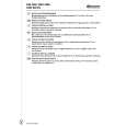
Color bar chart (Color reproduction adjustment frame )
H
Green
Electronic beam scanning frame
Magenta Red
C
C=D
D
Magenta Red Blue Yellow
CRT picture frame
V AB A=B BA Enlargement
Cyan Green White
Fig. a Video terminal output waveform
Effective picture frame
Fig. b (monitor TV picture) Difference in level Adjust the camera zoom and direction to obtain the output waveform shown in Fig. a and the TV monitor display shown in Fig. b.
B
A
Fig. 5-1-7
3. 1) Subjects Color bar chart (Color reproduction adjustment frame) When performing adjustments using the color bar chart, adjust the picture frame as shown in Fig. 5-1-7. (Standard picture frame) Clear chart (Color reproduction adjustment frame) Remove the color bar chart from the pattern box and insert a clear chart in its place. (Do not perform zoom operations during this time.) Flange back adjustment chart Make the chart shown in Fig. 5-1-8 using A0 size (1189mm � 841mm) black and white vellum paper.
White 841mm Black
2)
3)
1189mm
Fig. 5-1-8
Note: Use matte vellum paper bigger than A0, and make sure the edges of the black and white paper joined together are not rough.
5-6
|
|
|
> |
|