|
|
|
Who's Online
There currently are 5647 guests online. |
|
Categories
|
|
Information
|
|
Featured Product
|
|
|
 |
|
|
There are currently no product reviews.
 ;
Block diagram,play rec block diagram,adjusments, it's a very good well done repair manual.
 ;
Very clear copy of the philips service manual. Fast delivery. Thank you very much
 ;
Excellent manual, detailed, very useful! Exactly what I needed, I'd recommend it to all who need it. Although images are scanned easily readable and explicit. A valuable tool product at a price more than modest, take it with confidence and you will not regret it!
 ;
Clear and complete service manual. Easy now to restore my old Kenwood KD-1500.
Thanks a lot.
 ;
Thanks for this "hard to find" service manual. This Sony PS212A is a very good turntable that needed to be restored !
< DECK SECTION >
7. DC Balance / Mono Distortion Adjustment Settings : � Test point : TP3, TP4 (DC) � Adjustment location : L801 � Input level : 60dBµV Method : Set to FM 98.0MHz and adjust L801 to achieve minimum distortion. Then check that the voltage between TP3 and TP4 is within 0V ± 300mV. 8. Output Level Check <AM> Settings : � Test point : TP8 (Lch), TP9 (Rch) � Input level : 74dBµV Method : Set to AM 1000kHz <LH,U,HA>, AM 999kHz <HS> and check that the test point is 40mV ± 3dB. <FM> Settings : � Test point : TP8 (Lch), TP9 (Rch) � Input level : 60dBµV Method : Set to FM 98.0MHz and check that the test point is 140mV ± 3dB. 9. FM Separation Check Settings : � Test point : TP8 (Lch), TP9 (Rch) � Input level : 60dBµV Method : Set to FM 98.0MHz and check that the test point is more than 25dB. 10. Tape Speed Adjustment (DECK 2) Settings : � Test tape : TTA�100 � Test point : TP8 (Lch), TP9 (Rch) � Adjustment location : SFR1 Method : Play back the 3kHz signal of the test tape and adjust SFR1 so that the test point becomes 3000Hz ± 5Hz (FWD) and FWD SPEED ± 45Hz (REV). 11. Head Azimuth Adjustment (DECK 1, DECK 2) Settings : � Test tape : TTA�330 � Test point : TP8 (Lch), TP9 (Rch) � Adjustment location : Head azimuth adjustment screw Method : Play back (FWD) the 8kHz signal of the test tape and adjust screw so that the output becomes maximum. Next, perform on REV PLAY mode. 12. PB Frequency Response Check (DECK 1, DECK 2) Settings : � Test tape : TTA�330 � Test point : TP8 (Lch), TP9 (Rch) Method : Play back the 315Hz and 8kHz signals of the test tape and check that the output ratio of the 8kHz signal with respect to that of the 315Hz signal is 0dB ± 5dB. 13. PB Sensitivity Check (DECK 1, DECK 2) Settings : � Test tape : TTA�200 � Test point : TP8 (Lch), TP9 (Rch) Method : Play back the test tape and check that the output level of the test point is 110mV ± 3dB. 14. REC/PB Frequency Response Adjustment (DECK 2) Settings : � Test tape : TTA�602 � Test point : TP8 (Lch), TP9 (Rch) � Input signal : 1kHz / 8kHz (�20VU / �26dBV) � Adjustment location : SFR451 (Lch) SFR452 (Rch) Method : Apply a 1kHz signal and REC mode. Then adjust OSC attenuator so that the output level at the TP8, TP9 becomes 5.5mV ~ 9.5mV. Record and play back the 1kHz and 8kHz signals and adjust SFRs so that the output of the 8kHz signals becomes 0dB ± 0.5dB <LH,HA,HS>, �1.5dB ± 0.5dB <U> with respect to that of the 1kHz signal. 15. REC/PB Sensitivity Check (DECK 2) Settings : � Test tape : TTA�602 � Test point : TP8 (Lch), TP9 (Rch) � Input signal : 1kHz (0VU / �6dBV) Method : Apply a 1kHz signal and REC mode. Then adjust OSC attenuator so that the output level at TP8, TP9 becomes 55mV ~ 95mV. Record and play back the 1kHz signals and check that the output is �1dB ± 3.5dB.
� 28 �
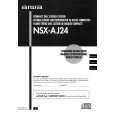
 $4.99 NSXAJ24 AIWA
Owner's Manual Complete owner's manual in digital format. The manual will be available for download as PDF file aft…
|
|
 |
> |
|
