|
|
|
Who's Online
There currently are 5737 guests online. |
|
Categories
|
|
Information
|
|
Featured Product
|
|
|
 |
|
|
There are currently no product reviews.
 ;
OEM manual provided all schematics, board layouts and component specs necessary to facilitate unit maintenance. All pages were clear and readable.
;
Good condition and quality. Hard to find anywhere in Internet, only on this site.
 ;
Exactly what I needed to be able to bring the amp back to life... will come back to this site the next time I need schematics.
;
Information was accurate and very helpful.
However the continuity made it a little difficult to follow from one page to the next.
;
Very very good as usual very trustable site. Perfect!!!!!!
4. With the REC MODE switch set to 48kHz (ATF: OFF) and the INPUT switch set to COAXIAL or ANALOG (OFFSET: + or �), fine adjust the S1 and T1 guides so that the oscilloscope RF signal waveform remains the same when high-low is repeated.
DPG Adjustment Perform the following adjustment without fail when the drum has been replaced. Procedure: 1. Connect oscilloscope CH-1 to JW183 (PBRF) and CH-2 to JW092 (SWP) on the main board. (Use CH-2 as the trigger.When the CH-2 signal is inverted, the trailing edge can be used for synchronization.) 2. Set the test mode (main) and load test tape TY-7252 (8-909-82200). 3. Set the REC MODE switch to LONG (ATF: ON) and the INPUT switch to OPT (OFFSET:0). 4. Press the AMS (+) key. �DPG� will be displayed on the fluorescent indicator tube. 5. Press the 0 and ) keys as appropriate so that the gap between the oscilloscope SWP and RF signals become 650 ± 15µsec. (Hold the 0 and ) keys down for more than 1 second to perform rough adjustment. Hold them down for approximately 0.2 seconds for fine adjustment, and the auto adjustment can be performed pressing PLAY (() key).
End Sensor Check Perform the following adjustment when the holder has been removed or part of the mechanism deck section replaced. Procedure: 1. Connect an oscilloscope to the JW158 (SEND: in the S side) and JW143 (TEND: in the T side) of the main board. 2. Set the test mode (main), mount an end sensor cassette and effect the STOP (p) mode. 3. Check that p-p values of waveform of the oscilloscope satisfy the following.
in the S side: 300 mVp-p or more
* Finish the adjustment by screwing in. 5. Check the RF signal waveform with the REC MODE switch set to LONG (ATF: ON) and the INPUT switch set to COAXIAL or ANALOG (OFFSET: + or�).
in the T side: 150 mVp-p or more
OK 4/5 A or less
Adjustment Location: � Mechanism assembly �
T1 guide
RF (PBRF) NG A
4/5 A' or less 650 ± 15 µsec NG A'
SWP T2 guide
AGC Voltage Check Perform this adjustment after cleaning the heads with a cleaning cassette.
S1 guide
6. Check the RF signalwaveform with the REC MODE switch set to LONG (ATF: ON) and the INPUT switch set to OPT (OFFSET: 0). (1) Confirm that the RF signal waveform peak value (B) is 60mV or more. (2) Confirm that the undershoot level of the RF signal waveform's flat portion is within 10%.
B/10 or less
B/10 or less B
Procedure: 1. Connect oscilloscope CH-1 to JW247 (GCA: Gain Control Amp.) and CH-2 to JW092 (SWP) on the main board. (When the CH-2 signal is inverted, the trailing edge can be used for synchronization.) 2. Set the test mode (main) and load test tape TY-7111X (8-909823-00). 3. Set the PLAY (() mode and check that the GCA waveform on the oscilloscope is as follows
1V
S2 guide
F guide
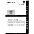
[MAIN BOARD] (Component side)
Test mode (Main)
Tape Path Fine, DPG, AGC Voltage
0V (When the output level or B ch is low)* IC310 GCA 1V JW143 (TEND)
JW091 (X TEST) JW092 (SWP) JW158 (SEND)
IC304
Tape Path Fine, DPG
7. When the measured values are not within the above tolerance repeat items 3 to 6 above. Adjustment Point: Mechanism assembly
CN341 JW183 JW247 (GCA)
0V (When the output level or A ch is low)* SWP End Sensor CN302
(PBRF)
AGC Voltage A ch B ch A ch FWD Torque RV451
* Slightly changes depending on the state of the head. NG if the GCA waveform is 1V or more or equal to the ground level.
� 19 �
� 20 �
|
|
|
> |
|