|
|
|
Categories
|
|
Information
|
|
Featured Product
|
|
|
 |
|
|
There are currently no product reviews.
 ;
The manual I purchased was just what I needed. I was glad to find a site where I can find so many manuals on a wide variety of products.
;
The best diagram that I used in a long time. Everything was right on te money. It was easy and fast. Iwoiuld but again when I need a service manual.
;
The manual is great help for me, i'm happy to have it,thanks
 ;
Very pleased with manual except that a few more details in the drawings might make the job (not yet done, tut-tut) easier. Should be adequate though. Actually I didn't have to pay for this anyway as I was given credit for another item that wasn't quite complete. Good service, then.
;
Very useful manuals, somewhere graphics not very clear!
1
2
3
4
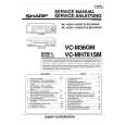
Charged Section
A
High Voltage Generating Point
The places where voltage is 100V or more except for the charged places described above. If the places are touched, there is a risk of electric shock. 1. SW POWER SUPPLY Module ...................................... (215V) 2. X DRIVE Assy ............................................... (�280V to 215V) 3. Y DRIVE Assy ................................................................(345V) 4. SCAN (A) Assy .............................................................. (345V) 5. SCAN (B) Assy .............................................................. (345V) 6. X CONNECTOR (A) Assy ............................ (�280V to 215V) 7. X CONNECTOR (B) Assy ............................ (�280V to 215V)
The places where the commercial AC power is used without passing through the power supply transformer. If the places are touched, there is a risk of electric shock. In addition, the measuring equipment can be damaged if it is connected to the GND of the charged section and the GND of the non-charged section while connecting the set directly to the commercial AC power supply. Therefore, be sure to connect the set via an insulated transformer and supply the current.
B
1. AC Power Cord 2. AC Inlet with Filter 3. Power Switch (S1) 4. Fuse (In the SW POWER SUPPLY Module) 5. STB Transformer and Converter Transformer (In the SW POWER SUPPLY Module) 6. Other primary side of the SW POWER SUPPLY Module
Y DRIVE Assy
C
: Part is Charged Section. : Part is the High Voltage Generating Points other than the Charged Section.
SCAN (A) Assy
Top
SCAN (B) Assy
Front
D
X CONNECTOR (A) Assy
� Remove the IF Earth Metal (No.14 on the page 25)
beforehand when inclines the power supply unit as the right figure.
X DRIVE Assy
X CONNECTOR (B) Assy
E
SW POWER SUPPLY Module AC Inlet with Filter Power Switch (S1)
Power Cord
Fig.1 Charged Section and High Voltage Generating Point (Rear View)
F
4
1 2
PDP-433PU
3 4
|
|
|
> |
|