|
|
|
Categories
|
|
Information
|
|
Featured Product
|
|
|
 |
|
|
There are currently no product reviews.
 ;
Clear and complete service manual. Easy now to restore my old Kenwood KD-1500.
Thanks a lot.
;
Thanks for this "hard to find" service manual. This Sony PS212A is a very good turntable that needed to be restored !
 ;
Excellent quality on these manuals. Same as having the original printed manual and incredibly useful when doing a custom install like me. Keep it up on the good work.
;
This is an excellent information source. Great quality and tons of info regarding technical service for the Technics SH8065.
;
5 stars on this manual since it is the complete version, not the half manual you find free for download all over the web. Good job.
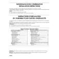
Alignment and Adjustments
IF GENERATOR
TUNER PART
EXT FM antenna : FTP1 75� Dummy SET
GND
Oscilloscope
PIN 19 OF FIC1 O GND O Input o output o FTP1 BODY O
FM SSG
GND
Speaker OUT
VTVM
GROUND O FTP2
Stereo Modulator (Pilot 10%)
OUT
3.2 ohm load
Fig 1-2
1-1-4 AM Adjustment
Step Item Intermediate frequency (IF) adjustment AM frequency coverage adjustment Connection SSG.FREQ. FREQ. Setting Adjust. Point Tune to the lowest Tune to the lowest Tune to the highest 600 KHz 1400 KHz AM IFT : IT 1(WHT) AM OSC COIL : OT 1 Remark
Fig 1-3
1-1-5 MW/LW
Step Item Intermediate frequency (IF) adjustment AM frequency coverage adjustment Fig 1-5 Connection SSG.FREQ. FREQ. Setting Adjust. Point Remark
1
Figure 1-5
455 KHz
Maximum output Best responding point of SSG
1
IF is the same as 2 band�s
Tune to the lowest Tune to the highest 600 KHz 1400 KHz Tune to the lowest Tune to the highest OT1 VC4 AM ANT COIL VC3 OT2 Best responding point of SSG Best responding point of SSG Maximum output Maximum output Best responding point of SSG Best responding point of SSG Maximum output
2 3 4 5
Figure 1-4
Connect DC voltmeter to AM VT(OR10) and GND
515 KHz 1680 KHz (1780)KHz 600 KHz 1400 KHz
2 3 4 5 6
515 KHz 1680 KHz 600 KHz 1400 KHz 145 KHz
OSC TRIMMER Best responding : VC4 point of SSG AM ANT COIL
Maximum output
AM tracking adjustment
Figure 1-5 -
ANT TRIMMER Maximum output : VC3
AM tracking adjustment
Fig 1-5
LW frequency coverage adjustment Fig 1-5
7
AM VT(OR10)
295KHz
OCT4
SET
GND
Input
DC Voltmeter
8
LW tracking adjustment Fig 1-5
170MHz 250 MHz
170 MHz 250 MHz
LW ANT COIL
Figure 1-4
VTVM AM Signal Generator
Test Loop Antenna IN OUT AM-ANT Speaker Terminal
Oscilloscope
9
Not required
SET
60 cm GND
Dummy Load(3�)
Figure 1-5 1-2 Samsung Electronics
|
|
|
> |
|