|
|
|
Categories
|
|
Information
|
|
Featured Product
|
|
|
 |
|
|
There are currently no product reviews.
 ;
This manual is all I need to check and repair my equipment. Thank you....
;
this manual make me repair my vintage radio with easily.
Thank you for your best service
sukpra
;
A good manual. Had everything i needed to make the repair.
;
This manual is a complete guide, including later additions. It has all the necessary information about the replacement items. The material quality is great to read.
 ;
This manual is very helpful, correct shematic diagram, and good exploded view.Perfect!
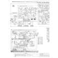
SECTION 4 DIAGRAMS
Note on Schematic Diagram: � All capacitors are in µF unless otherwise noted. pF: µµF 50 WV or less are not indicated except for electrolytics and tantalums. � All resistors are in � and 1/ W or less unless otherwise specified.
4
RM-NX7000
Note on Printed Wiring Board: � X : parts extracted from the component side. � Y : parts extracted from the conductor side. � : Pattern from the side which enables seeing. (The other layers' patterns are not indicated.) Caution: Pattern face side: (Side B) Parts face side: (Side A) Parts on the pattern face side seen from the pattern face are indicated. Parts on the parts face side seen from the parts face are indicated.
� % : indicates tolerance. � C : panel designation. � A : B+ Line. � Power voltage is dc 4.5V and fed with regulated dc power supply from extermal power voltage jack. � Voltages and waveforms are dc with respect to ground under nosignal conditions. no mark : POWER ON � Voltages are taken with a VOM (Input impedance 10 M�). Voltage variations may be noted due to normal production tolerances. � Waveforms are taken with a oscilloscope. Voltage variations may be noted due to normal production tolerances. � Circled numbers refer to waveforms.
� Main boards is six-layer pritnted board. However, the patterns of layer 2 to 5 have not been included in this diagrams.
� IC1 (microcomputer) and IC7 (flash RAM) on Main board cannot be replaced individually. Replace it with Main board assembly for service.
� IC1 (microcomputer) and IC7 (flash RAM) on Main board cannot be replaced individually. Replace it with Main board assembly for service. * The voltage and waveform of CSP (chip size package) cannot be measured, because its lead layout is different form that of conventional IC.
� WAVEFORMS
� MAIN BOARD �
1
IC701 ej
XT2
3.2 Vp-p
32.768KHz
VOL/DIV : 1 V AC TIME/DIV : 20 µsec
2
IC701 r;
X2
3 Vp-p
5MHz
VOL/DIV : 1 V AC TIME/DIV : 0.1 µsec
9
9
|
|
|
> |
|
|
Parse Time: 0.14 - Number of Queries: 100 - Query Time: 0.03