|
|
|
Categories
|
|
Information
|
|
Featured Product
|
|
|
 |
|
|
There are currently no product reviews.
 ;
Good pdf of the service manual for this unit. Includes disassembly instructions, full schematics, board layouts, parts lists and diagnostic information. Some information is in the pdf twice (single pages, and split pages), but that could be how it was originally generated by panasonic, or perhaps the idea is to make it eaiser to put onto 8.5 x 11" pages.
Information was exactly what I needed. Delivery was overnight (less than 12 hours) and I was happy with the process.
;
5 STARS for FAST DELIVERY, BEST PRICES and QUALITY PRODUCT. Item was exactly as described with superb resolution. Will definitely source all my future requirements from this website. Thanks a lot owner-manual.com!
;
OEM manual provided all schematics, board layouts and component specs necessary to facilitate unit maintenance. All pages were clear and readable.
;
Good condition and quality. Hard to find anywhere in Internet, only on this site.
 ;
Exactly what I needed to be able to bring the amp back to life... will come back to this site the next time I need schematics.
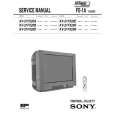
1-4-5. V Board
Removal 1. Remove the base assembly. (Refer to Section 1-3-1.) 2. Remove the rear cover and rear panel. (Refer to Section 1-3-3.) 3. Remove the two hooks of the rear panel, then remove the V board. 4. Disconnect the harness from the connector (CN30) on the V board.
1-4-6. Lamp Power Supply Board
Removal 1. Remove the cabinet. (Refer to Section 1-3.) 2. Remove the C board. (Refer to steps 3 to 6 of Section 1-4-1.) 3. Remove the lamp assembly. (Refer to steps 2 and 3 of Section 1-5-2.) 4. Remove the three screws and disconnect the harness from the connector (CN14) on the F board, then remove the lamp power supply unit. 5. Remove the two screws, then remove the lamp house. 6. Loosen the two screws, then remove the connector.
BTP 3 x 12 Lamp power supply unit
Rear panel
Hooks
CN30
BTP 3 x 12 Lamp house Screws
Harness
V board
Connector
Installation 5. Install the V board in the reverse order of steps 3 and 4. 6. Assemble this unit in the reverse order of steps 1 and 2.
Harness
CN14
F board
1-8
VPL-HS60/HS51A
|
|
|
> |
|