|
|
|
Who's Online
There currently are 6043 guests online. |
|
Categories
|
|
Information
|
|
Featured Product
|
|
|
 |
|
|
There are currently no product reviews.
 ;
got exactly what i ordered in a very timely manner. will use again for other manuals
 ;
I'm happy. Good quality. Very helped me with my work..............................
;
This is the second Manual I have ordered from owner-manuals, I give it five stars because it is exactly what I expected given the age of the equipment. So the contents look a bit aged and the pictures a bit grainy, it fulfills my needs and I am glad I can still get hold of them.
;
thank u so much for this manual that was so cheap that i thought it was a scam but i gambled anyway because it was too good of a deal to pass up and behold,the manual has everything and details of everything even the screws and im still amazed and very happy with my manual .so take my word and jump on it before they realize how cheap they selling thier manuals..thank you so much for taking time to read my thoughts
;
I do not have very much to say.
The price is quite covenient, delivery was better as promised (about 12 ours, against the specified 24 hours if I remember well), and the quality of the PDF is more than acceptable.
The Service Manual of Sansui R30 itself is also satisfactory: good graphic for schematics and layouts, simple and well structured.
Giovanni Bianchi
RX-7022RSL/RX-7020RBK
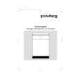
Removing the audio board (See Fig.10)
Relay board power supply board CN291 Power transformer Power / Fuse board
Prior to performing the following procedure, remove the top cover and the rear panel. 1. Disconnect the card wire from connector CN402 CN403 on the audio board. 2. Disconnect the relay board from the audio board and the power supply board. (CN291, CN491) 3. Disconnect the harness from connector CN471, CN472, CN473. 4. Remove the three screws G board assembly. 5. Remove the screw H assembly. attaching the audio
CN403 CN473
G
CN402
G
Audio board CN472 CN471
G CN491 H
Fig.10
attaching the audio board
I
(See Fig.11)
CN241
Removing the main board
Prior to performing the following procedure, remove the top cover, the rear panel and audio board. 1. Disconnect the harness from connector CN241 and CN203 on the power supply board respectively. 2. Disconnect the harness from connector CN251 on the power transformer board . 3. Remove the four screws I and the two screws J attaching the main board.
I J I
Main board
J
CN251
CN203
I
Fig.11
Removing the heat sink (See Fig.12 to 14)
Prior to performing the following procedure, remove the top cover and main board. 1. Remove the two screws K attaching the heat sink to the reverse side of main board. 2. Disconnect the for connectors with each amp. board, and remove the main board.
K
K
Fig.12
Main board rear side
Front Rch amp. board Heat sink Front Lch amp. board Center amp. board
3. Remove the four screws M and ten screws L Rear Lch amp. board attaching the heat sink. Rear Rch amp. board
Heat sink
L
L
L M
Main board
M
CN802 CN801 CN302 CN301
CN901
Fig.14
Fig.13
1-5
|
|
|
> |
|