|
|
|
Categories
|
|
Information
|
|
Featured Product
|
|
|
 |
|
|
There are currently no product reviews.
 ;
Very comprehensive document which is a must-have for any Satellit 2100 owner whose set up is somewhat intricate. Due to the bad quality of the pictures that are rather dark and a bit blurred I gave 4-star feedback.
;
The manual was missing 2 pages but when I presented the problem to the company they made every attempt to get the 2 pages to me, when they couldn't they refunded my money. A very pleasing and easy transaction. The manual they provided was the original, it was concise and to the point. I plan to do business with this company again when should the need arise.
 ;
The owners manual is very good. all my how to questions were answered in detail.
;
Irrespectively of this manual exist only germany language, it's useful - although i need some additional task to translate: My english is bad, but usable - but i really dont speak germany. :)
;
Excellent service from this company (including a total refund on an earlier purchase when through no fault of the company the manual was incomplete). I have purchased several manuals which I have been very satisfied with, as I am with this one. Highly recommended.
SAT-A55/B55 FOR SATELLITE ANTENNAS:
Input Frequency Output Frequency Output Connector
12.2 - 12.7 GHz 950 - 1450 MHz F-Type Female
Supplied Accessories
Weatherboot 2pcs Signal Seeker 1pc Snap-in Clip (dual type) 1pc Bolt for Ground Terminal 1pc Bolt for LNB Support Arm 2pcs
Power Consumption 3.0 W max. Supply Voltage
DC + 10.5 - 14.0 V for RHCP DC + 15.5 - 21.0 V for LHCP
Optional Accessories
Dimensions (w/h/d) 185/8 x 31 x 185/16 inches
473 x 787 x 643 mm
Installation Kit ANJ-DS2 Amplifier EAC-DA1 Diplexer EAC-DD1 Voltage Switch ECA-DV2 Multi-Room A/V Distribution System MDR-D1 Coaxial Cable 25' SAK-C25 Coaxial Cable 75' SAK-C75 Flat Cable SAK-F1
Weight
8 lbs 6 oz (3.8 kg)
SAFETY CHECK-OUT
1. Check the area of your repair for unsoldered or poorlysoldered connections. Check the entire board surface for solder splashes and bridges.
5. Look for parts which, though functioning, show obvious signs of deterioration. Point them out to the customer and recommend their replacement.
2. Check the interboard wiring to ensure that no wires are SAFETY CHECK-OUT line cords for cracks and abrasion. Recom6. Check the �pinched� or contact high-wattage resistors. mend the replacement of any such line cord to the customer. 3. Check that all control knobs, shields, covers, ground straps, and mounting hardware have been replaced. Be 7. Check the B+ and HV to see if they are specified absolutely certain that you have replaced all the insulators. values. Make sure your instruments are accurate; be suspicious of your HV meter if sets always have low HV. 4. Look for unauthorized replacement parts, particularly transistors, that were installed during a previous repair. Point them out to the customer and recommend their 8. Check the antenna terminals, metal trim, �metallized� replacement. knobs, screws, and all other exposed metal parts for AC leakage using one of the methods listed. LEAKAGE TEST The AC leakage from any exposed metal part to earth ground and from all exposed metal parts to any exposed metal part having a return to chassis, must not exceed 0.5 mA (500 microamperes). Leakage current can be measured by any one of three methods. 1. A commercial leakage tester, such as the Simpson 229 or RCA WT-540A. Follow the manufacturers� instructions to use these instruments. 2. A battery-operated AC milliammeter. The Data Precision 245 digital multimeter is suitable for this job. 3. Measuring the voltage drop across a resistor by means of a VOM or battery-operated AC voltmeter. The �limit� indication is 0.75 V, so analog meters must have an accurate low-voltage scale. The Simpson 250 and Sanwa SH-63Trd are examples of passive VOMs that are suitable. Nearly all battery operated digital multimeters that have a 2 VAC range are suitable. (See Figure 1)
Figure 1. Using an AC voltmeter to check AC leakage.
�3�
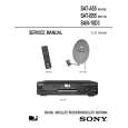 $4.99 SAT-B55 SONY
Service Manual Complete service manual in digital format (PDF File). Service manuals usually contains circuit diagr…
|
|
|
> |
|