|
|
|
Categories
|
|
Information
|
|
Featured Product
|
|
|
 |
|
|
There are currently no product reviews.
 ;
Good manual. It is complete and of high quality, both text and graphics. The schematics are with the original big size, so it can be viewed or printed without any loss of resulution and sharpness.
;
We needed a manual quickly...online it was available immediately, at a very low price. We loved the convenience!
;
Excellent!!
Got what I need and very fast!!
Thank You
;
One address for rare manuals.Very good copy. Thank you.
Your
Klaus Husse
;
All ok. I pay 5 $ and now i have 92 pages of good scaned service manual for my oooooold akai. Now i will try to repair it.
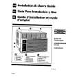
SAT-HD100
1-4. A, G & TU BOARD REMOVAL
4
5
6
7
8
9
3
2 1
Note: For board removal or replacement, detach all attached cables, and leave them attached to an existing board.
10 11
7
1 2 3
Detach the connector between the A and G Boards. Remove (2) screws (+BVTT 3 x 12) from G Board. Remove (1) screw (+BVTP 3 x 8) from G Board. Gently lift the board forward and up to remove. Remove (1) screw (M3 x 6) from the back panel holding in the tuning unit. Remove (2) hex nuts from the cable jacks. Remove (2) screws (+BVTP 3 x 8) from the back of the unit, mounting the fan assembly. Lift the assembly up and out to remove.
Remove (2) screws (M3 x 6) from the back of the unit, mounting the RF Remote Assembly. Lift the assembly up and out to remove. Remove (2) screws (+BVTP 3 x 8) from the back of the unit at the RCA jacks. Remove (2) screws (+BVTT 3 x 12) mounting the TU Board to chassis. Remove (4) screws (+BVTT 3 x 12) mounting A Board to Chassis. Gently lift the A and TU Boards simultaneously forward and up to remove. Support the weight of both boards at the connector. Once removed from the chassis, disconnect the connector shown to separate the A and TU Boards.
8
4 5 6
�8�
|
|
|
> |
|
|
Parse Time: 0.161 - Number of Queries: 102 - Query Time: 0.036