|
|
|
Categories
|
|
Information
|
|
Featured Product
|
|
|
 |
|
|
There are currently no product reviews.
 ;
complete part-lists and pcb layout, schematic diagram is good enlargable,
;
Excellent, fast delivery, excellent product. Good luck!
;
This manual is for the usa model only. But it is clear
, accurate and comprehensive, including board layouts and schematics.
I found it extremely useful for my mitsubishi dp-86da, but the same diagram would also work for the realistic lab5000 and hi fi 80. Thanks.
;
Great to have extra resources for Service Manuals, Now days you can really not trouble shoot efficiently without one , Wayne at IRIONS TV & ELECTRONICS REPAIR Clearwater , Fl. 33755 727-446-7955
 ;
For five bucks you can barely buy a hamburger. Or for the same five bucks you can buy a service manual. Much more useful. (and better for your health, depending on where you buy your hamburgers).
Yes, there are free manual sites out there, but if they don't have what you want, you have to pay.
And five bucks isn't much. Not for full specs, schematics and adjustment and parts replacement procedures.
My only criticism is that grayscale illustrations aren't well rendered, but I've seen worse.
Schematics and text are clear.
I'll be happy to purchase from here again.
Mike
mikeinthemountains@gmail.com
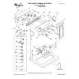
CD SECTION
Note: 1. CD Block is basically designed to operate without adjustment. Therefore, check each item in order given. 2. Use YEDS-18 disc (3-702-101-01) unless otherwise indicated. 3. Use an oscilloscope with more than 10M impedance. 4. Clean the object lens by an applicator with neutral detergent when the signal level is low than specified value with the following checks. 5. Adjust the focus bias adjustment when optical block is replaced. Focus Bias Adjustment
oscilloscope CD board TP (RF) TP (VC)
S Curve Check
oscilloscope CD board TP (FEO) TP (VC)
Procedure : 1. Load CDs into the each tray (seven pieces). 2. Connect oscilloscope to test point TP (FEO). 3. Connect between test point TP (FOK) and Ground by lead wire. 4. The focus search is performed by turning ON the SYSTEM POWER. It searches DISC 1-7 in order and stops. 5. Check the oscilloscope waveform (S-curve) is symmetrical between A and B. And confirm peak to peak level within 2.4 ± 0.7 Vp-p.
S-curve waveform symmetry
Procedure: 1. Connect oscilloscope to test point TP (RF). on CD board. 2. Turned SYSTEM POWER switch on. 3. Put disc (YEDS-18) in to playback the number two track. 4. Adjust RV101 so that the waveform is clear. (Clear RF signal waveform means that the shape � � can be clearly distinguished at the center of the waveform.) 5. After adjustment, check the RF signal level.
� RF signal VOLT/DIV: 200 mV TIME/DIV: 500 nS
A
within 2.4 ± 0.7 Vp-p
B
6. After check, remove the lead wire connected in step 3. Note: � Try to measure several times to make sure than the ratio of A : B or B : A is more than 10 : 7. � Take sweep time as long as possible and light up the brightness to obtain best waveform. RF Level Check
oscilloscope CD board TP (RF) TP (VC)
level: 1.2 ± 0.2 Vp-p
Procedure : 1. Connect oscilloscope to test point TP (RF) on BD board. 2. Turned SYSTEM POWER switch on. 3. Put disc (YEDS-18) in to playback the number two track. 4. Confirm that oscilloscope waveform is clear and check RF signal level is correct or not. Note: Clear RF signal waveform means that the shape � � can be clearly distinguished at the center of the waveform.
RF signal waveform VOLT/DIV: 200 mV TIME/DIV: 500 nS level: 1.2 ± 0.2 Vp-p
� 33 �
 $4.99 SAVA100 SONY
Owner's Manual Complete owner's manual in digital format. The manual will be available for download as PDF file aft…
|
|
|
> |
|