|
|
|
Categories
|
|
Information
|
|
Featured Product
|
|
|
 |
|
|
There are currently no product reviews.
 ;
This is a service manual in every sense of the word ( French and German versions of the text are included, as well as English..)
There are explanations of the mechanical and electrical functions, plenty of mechanical drawings, and the needed schematics. The quality of the scanning is excellent - all the component values are clearly legible - and very usefully there are pcb component layouts, so you can find a component on the schematic, and then very quicky pinpoint its physical location on the relevant pcb.
I cannot see how I can give this manual any less than the maximum 5 stars! Great value for money, which will pay for itself immediately. Excellent all round!
;
the manual is great and especially hard to find... thanks for the great service and having a hard to find manuel_
;
Please tell us what you think and share your opinions with others. Be sure to focus your comments on the product. You will receive $2.50 of store credit for Your review.
;
hat alles sehr gut geklappt. Das Servicemaual ist gut zu verwenden. Die Pläne und Schrift
ist klar und leserlich. Außerdem preiswert. Grüße an alle Hifi-Bastler
;
I got the manual quickly after the payment was transfered (1 day). The manual was exactly what i needed and the updates via e-mail were great. Thanx!
SA-VE335/WMS335/SS-CN335/V335
SAFETY CHECK-OUT
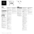
After correcting the original service problem, perform the following safety check before releasing the set to the customer: Check the antenna terminals, metal trim, �metallized� knobs, screws, and all other exposed metal parts for AC leakage. Check leakage as described below. LEAKAGE TEST The AC leakage from any exposed metal part to earth ground and from all exposed metal parts to any exposed metal part having a return to chassis, must not exceed 0.5 mA (500 microamperes). Leakage current can be measured by any one of three methods. 1. A commercial leakage tester, such as the Simpson 229 or RCA WT-540A. Follow the manufacturers� instructions to use these instruments. 2. A battery-operated AC milliammeter. The Data Precision 245 digital multimeter is suitable for this job. 3. Measuring the voltage drop across a resistor by means of a VOM or battery-operated AC voltmeter. The �limit� indication is 0.75 V, so analog meters must have an accurate low-voltage scale. The Simpson 250 and Sanwa SH-63Trd are examples of a passive VOM that is suitable. Nearly all battery operated digital multimeters that have a 2V AC range are suitable. (See Fig. A)
TABLE OF CONTENTS 1. DIAGRAMS
1-1. Circuit Boards Location (SA-WMS335) ............................ 3 1-2. Printed Wiring Boards (SA-WMS335) ............................... 5 1-3. Schematic Diagram (SA-WMS335) ................................... 6
2. EXPLODED VIEWS
2-1. 2-2. 2-3. 2-4. Front Panel Section (SA-WMS335) .................................... 7 Rear Panel Section (SA-WMS335) ..................................... 8 Front and Rear Speaker (SS-V335) ..................................... 9 Center Speaker (SS-CN335) ............................................. 10
3. ELECTRICAL PARTS LIST ........................................ 11
To Exposed Metal Parts on Set
0.15µF
1.5k�
AC voltmeter (0.75V)
Earth Ground
Fig. A. Using an AC voltmeter to check AC leakage.
SAFETY-RELATED COMPONENT WARNING!! COMPONENTS IDENTIFIED BY MARK 0 OR DOTTED LINE WITH MARK 0 ON THE SCHEMATIC DIAGRAMS AND IN THE PARTS LIST ARE CRITICAL TO SAFE OPERATION. REPLACE THESE COMPONENTS WITH SONY PARTS WHOSE PART NUMBERS APPEAR AS SHOWN IN THIS MANUAL OR IN SUPPLEMENTS PUBLISHED BY SONY.
ATTENTION AU COMPOSANT AYANT RAPPORT � LA S�CURIT�!! LES COMPOSANTS IDENTIFI�S PAR UNE MARQUE 0 SUR LES DIAGRAMMES SCH�MATIQUES ET LA LISTE DES PI�CES SONT CRITIQUES POUR LA S�CURIT� DE FONCTIONNEMENT. NE REMPLACER CES COMPOSANTS QUE PAR DES PI�CES SONY DONT LES NUM�ROS SONT DONN�S DANS CE MANUEL OU DANS LES SUPPL�MENTS PUBLI�S PAR SONY.
2
|
|
|
> |
|