|
|
|
Who's Online
There currently are 6043 guests online. |
|
Categories
|
|
Information
|
|
Featured Product
|
|
|
 |
|
|
There are currently no product reviews.
 ;
Sweet! I won the item on eBay and couldn't adjust the geometry or even keep a steady picure. This guide has the full schematics (not available anywhere else as far as I could tell), and was a bargain for the wealth of knowledge it contains. I hooked it up to my testing equipment, tweaked a few potentiometers and got it playing videogames in no time. Thanks!
;
It was just what I need to fix my old BMW's CD player. Very convenient also. Thank you.
;
Great Manual! It contains all the wiring schematics and mechanical exploded views that are essential for service and repair. I was surprised I even found this for such an old machine. Only wish I knew of this site many years ago.
;
Great manual very clear copied. You are making an incredible job. I appreciate a lot the rapidity and your efficiency. Thanks a lot
;
Good pdf of the service manual for this unit. Includes disassembly instructions, full schematics, board layouts, parts lists and diagnostic information. Some information is in the pdf twice (single pages, and split pages), but that could be how it was originally generated by panasonic, or perhaps the idea is to make it eaiser to put onto 8.5 x 11" pages.
Information was exactly what I needed. Delivery was overnight (less than 12 hours) and I was happy with the process.
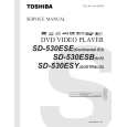
DECK MECHANISM DISASSEMBLY
Fig. 4-1
Fig. 4-2
1. Holder Clamp (Fig. 4-1)
1) Release 2 Screws(S1). 2) Unhook 2 Locking Tabs(L1). 3) Lift up the Holder Clamp and then separate it from the Base Main.
2. Tray Disc (Fig. 4-2)
1) Insert and push a Driver in the emergency eject hole(A) at the right side, or put the Driver on the Lever(B) of the Gear Emergency and pull the Lever(B) in direction of arrow so that the Tray Disc is ejected about 15~20mm. 2) Pull the Tray Disc until it is separated from the Base Main completely.
1-1. Clamp Assembly Disc
1) Place the Clamp Assembly Disc as Fig. (A) 2) Lift up the Clamp Assembly Disc in direction of arrow(A). 3) Separate the Clamp Assembly Disc from the Holder Clamp. 1-1-1. Plate Clamp 1) Turn the Plate Clamp to counterclockwise direction and then lift up the Plate Clamp. 1-1-2. Magnet Clamp 1-1-3. Clamp Upper
4-2
|
|
|
> |
|