|
There are currently no product reviews.
 ;
Excellent!! Got what I need and very fast!! Thank You
;
Manual acquired with good resolution, complete in all its pages, very good policy of the folder where are saved all products purchased.
 ;
Service manual very complete and clear. It was very helpfull for my work.
;
This is the 2nd time I download manuals from this website and I can say it's what I was expecting. It contains schematic, layout (decent quality), short description, parts and dissasembly instructions. I recomend it for anyone who wants to repair/modify this device.
;
Very useful Service Manual! With it I was able to identify the damaged pots in my old amplifier, purchase the adequate replacements and make myself the repair.
I have again my old amplifier, still a very good one that I will keep for as many years as I can!
Thanks to Owner Manuals!
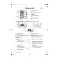
5-2.
HANDSET SECTION
3. Checking TX output Setting:
peak power meter + � ANTENNA TERMINAL
� Make the set in Test mode (see page 24) 1. Checking RX I&Q Output Level Setting:
oscilloscope + � level meter + � TP520: RXIP TP521: RXIN TP522: RXQP TP523: RXQN TP553: GND
Procedure: 1. Place the handset in the Continuous Transmit mode (CH1, High power). 2. Measure the ANT OUT output of the RF module in the handset using a peak power meter. 3. Confirm that the measured output is 62 mW (MIN 25 mW). 4. Also, execute steps 1 through 3 for the channels 10 and 20. CH10: 64 mW (MIN 25 mW) CH20: 64 mW (MIN 25 mW)
SSG
ANTENNA TERMINAL
Procedure: 1. Place the handset in the Continuous Receive mode (CH1, LNA, AGC ON). 2. Set the SSG frequency to the frequency on CH1 + 300 kHz, and the RF output level to �95 dBm. 3. Measure the output level of RXIN, RXIP, RXQN, and RXQP with a level meter. At this time, confirm with an oscilloscope that a sine wave of 300 kHz is output. 4. Confirm that the measured output level is �25.0 to �19.0 dBV. If IC502 was replaced (there is no ID data), the output level is �30.0 to �24.0 dBV. 5. Also, execute steps 1 through 4 for the channels 10 and 20. * For the frequency on each channel, see page 18.
2. Checking TX Center Frequency Setting: � short: TP555 � TP553
frequency counter + � ANTENNA TERMINAL
Procedure: 1. Short TP555 and TP553 (GND) on the HAND MAIN board in the handset. 2. Place the handset in the Continuous Transmit mode (CH1, High power). 3. Measure the ANT OUT frequency of the RF module in the handset using a frequency counter. 4. Confirm that the measured frequency is 903.600 MHz ± 27 kHz. 5. Also, execute steps 1 through 4 for the channels 10 and 20.
� 29 �
 $4.99 SPPA957 SONY
Owner's Manual Complete owner's manual in digital format. The manual will be available for download as PDF file aft…
|