|
|
|
Who's Online
There currently are 6043 guests online. |
|
Categories
|
|
Information
|
|
Featured Product
|
|
|
 |
|
|
There are currently no product reviews.
 ;
- Very good scan quality, PERFECT!
- Sehr gute scan Qualitaet, empfehlenswert!
Wolfgang Sundhaus
 ;
Good site, works ok and you get what you order, no problems experienced, got my manual within a day. A++++
;
Original well scanned manual. Got the job done. Microwave problem found & corrected. For $5 and a new magnitron from ebay, it was a cheap and good the first shot fix. Electrical schematics allowed me to mage sure every thing else was ok before cutting and order for parts. Hard to live without.
;
I was very skeptical of this website, I have never downloaded manuals before. I put it on the AMEX and payed through Paypal to ensure protection. I got the manual exactly as described and now I can replace the filter capacitor for this amp. Great Price, others selling for 12.99 or more and this is the same manual. I will search out this website for other manuals. Thank you
;
Manual was reasonably easy to follow. I am not an engineer or know much about electronics but with the manuals help I was able to figure out the problem, identify the part required for the repair. Replacement part cost around $30. Whilst replacing the part I was telling myself, "this aint gonna work cos it seems far too easy". Took about 15 minutes to do and my plasma TV works a treat. Would never have been able to do this without the service manual.
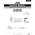
3-16. Crescent Slide
1. Refer to Section 3-2 and remove the mechanism unit. When you do this, make sure the mechanism is in EJECT mode. 2. Refer to Section 3-3-1 and remove the cassette mechanism assembly. 3. Refer to Section 3-7-2 and remove the capstan brake assembly. 4. Refer to Section 3-12-4 and remove the T soft brake assembly.
A 4 Crescent slide 6 Hole B 1 Screw
2 Crescent mounting
3 Clamp 0 Hole
8 Hole
C
5. Refer to Section 3-13-1 and remove the T brake act slide. 6. Refer to Section 3-12-1, then remove the reel belt and the reel pulley. 7. Refer to Section 3-15, then remove the wheel gear 2 and the main cam. 8. Refer to Section 3-13-2, then remove the wheel gear 1 and the brake control lever. 9. Remove the two screws 1, then remove the crescent mounting 2. 10. Remove the clamps 3, then raise the right end of the crescent slide 4 slightly. Slide the crescent slide 4 to the right until it comes away from the clamp 5, then remove it. Assembly Notes: 1. Apply grease (VHJ-0100) to the points A, B, C and D in Fig. 3-16-1, and to the crescent slide 4 shown in Fig. 3-16-2. 2. Before fitting the crescent slide 4, refer to Section 313-3 and align the arrow on the S brake act slide with the arrow on the mechanism chassis. Then refer to Fig. 3-17-3 and check that the S load gear and the T load gear have completed tape unloading. 3. When assembling the parts, raise the right side of the crescent slide 4 slightly, and keeping it in this position, slot the left side into the clamp 5, then align the hole 6 with the hole 7 in the mechanism chassis. When you do this, check that the hole 8 is aligned with the pin 9 on the BT spring lever assembly, and that the hole 0 is aligned with the pin !- on the S brake act slide, before pressing the crescent slide 4 into place. Check that the clamps 3 and 5 are engaged. 4. After assembly, check that each lever and each brake is working properly.
D 7 Hole 5 Clamp
9 Pin !- Pin
Fig. 3-16-1
Apply grease to the areas shown in � The places marked by dots should be greased particularly generously.
Grease the sides
Grease the teeth
Crescent slide
Fig. 3-16-2
SVT-RA40/RA168
2-29
|
|
|
> |
|