|
|
|
Categories
|
|
Information
|
|
Featured Product
|
|
|
 |
|
|
There are currently no product reviews.
 ;
the big video recorder format s-vhs many features delicate in loading system of the cassette. Such machines are no longer manufactured, it would be too expensive.
 ;
THIS MANUAL IS VERY GOOD AND VERY CLEAR
PLEASE NOTE IT DOES NOT CONTAIN THE SETUP INFORMATION TO ALIGHN THE GEARS IN THE CD MECH IT DOES SHOW ALL THE PARTS AND THEIR LOCATIONS .
;
Complete service and operation manual. All schematics are there, all circuit boards AND add-on boards. Including exploded views ,component names and specifications. Also electrical and mechanical adjustment procedures are in this manual. This manual also covers the more advanced BR-S811E unit. Scan quality is fair and usable.
;
High quality scan of original Service Manual. Everything´s fine!
;
Good scan of the original service manual. All schematics and adjustment procedures are there. It helped me to fix a long lasting problem with the tracking circuitry. The manual also includes the supplementals 1,2 and 3. Included are; electrical schematic's , pcb layout's, mechanical drawing's and exploded views, disassembly manual and maintenance procedures. 236 pages.
3.1.6 Removing the DSP board (See Figs.9 and 10) � Prior to performing the following procedures, remove the top panel and rear cover. (1) From the top side of the DSP board, disconnect the card wires from the connectors CN401 on the DSP board. (See Fig.10) (2) Remove the screw K attaching the DSP board from the section d of the barrier. (See Fig.10) (3) From the back side of the main body, remove the screw L and two screws M attaching the DSP board. (See Fig.9) Reference: � When attaching the DSP board, hang the DSP board on the section d of the barrier. (See Fig.10)
L
M
N
Fig.9
Rear panel
Section d
3.1.7 Removing the tuner (See Figs.9 and 11) � Prior to performing the following procedures, remove the top panel, rear cover and DSP board. (1) From the top side of the tuner, disconnect the card wire from the connector CN1 on the tuner. (See Fig.11) (2) From the back side of the main body, remove the two screws N attaching the tuner. (See Fig.9) (3) Take out the tuner from the main body.
K
CN401
DSP board
Fig.10
Tuner
Fig.11
CN1
(No.MB055)1-9
 $4.99 TH-A55 JVC
Circuit Diagrams Set of circuit diagrams. The diagrams will be provided as PDF file. The file will be delivered after… 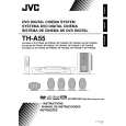 $4.99 TH-A55 JVC
Owner's Manual Complete owner's manual in digital format. The manual will be available for download as PDF file aft… 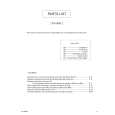 $4.99 TH-A55 JVC
Parts Catalog Parts Catalog only. It's available in PDF format. Useful, if Your equipment is broken and You need t…
|
|
|
> |
|